Rendering 1 Million spheres: Part 1 (OpenGL basics)
Hey everyone
So, I came across one problem statement on Twitter posted by Vipul Vaibhav and tried to implement it. It goes like this
Physically Based Rendering 1,000,000 spheres with unique materials supporting dynamic lighting and have sphere selection/highlighting ability while maintaining 60 FPS.
I didn’t have much experience with openGL before. I had written some GLSL shaders earlier, without interacting with openGL directly. So, I took my time to learn openGL and other important concepts like Physically Based Rendering, Image Based Lighting and basic matrix operations.
In this post, I’ll write about the basics of openGL and almost everything we need to know before implementing the main solution (obviously I’ll cover PBR and IBL in separate post).
One important thing before we start, the language of all these posts will not be that much formal. I’m keeping it light and conversational. Also, I’m writing all these posts based on my own understanding and it might not match yours.
I also want to mention that I learned and cleared my basics from learnopengl.com and FreeCodeCamp video on openGL. I’ll keep mentioning these resources at right places, so you can go and look through those topics in detail.
Let’s start now.
Basic setup
I used Visual Studio 2022 on Windows 11, with an NVIDIA RTX A1000 Laptop GPU and 12 GB RAM. With this GPU, we can render approximately 1.5-4 million visible vertices/frame even with complex calculations like Physically Based Rendering (PBR) and Image-Based Lighting (IBL), whilw maintaining 60 fps on screen. You just check your configurations and the limits of your GPU.
I assume that you have a decent understanding of C++ and Object Oriented Programming concepts, since once we cover the basics, we’ll refactor our code to follow OOP principles.
For OpenGL, we are not going to use the OpenGL functions directly as they are written by the GPU providers. Instead we will use GLFW, a library written in C, which provides all basic necessities for rendering and to create OpenGL context and handling windowing and input.
You can build GLFW package using CMake GUI or CLI as described on learnopengl.com’s Building GLFW section or directly use a pre-compiled package for your system. We’ll also have to link this library with our compilation process. For Visual Studio setup, you can follow this section from learnopengl.com.
If you ever want to compile your C++ code with external libraries, you can link them by adding -l<libraryname> during compilation.

eg.
g++ -o main main.cpp -lglfw3 -lGL
We’ll also need one more library: GLAD, it helps in loading the actual openGL function implementations it needs and store them in separate function pointers for later use. This is a system specific process, and you can follow it’s setup process from here on learnopengl.com.
Creating a window
Let’s start by creating main.cpp file. Inside it, we’ll include both GLFW and GLAD, and define main() function. We’ll initialize glfw with glfwInit(). Then we’ll have to configure it by specifying the openGL version (3.3) and setting openGL profile type(CORE).
int main()
{
    glfwInit();
    glfwWindowHint(GLFW_CONTEXT_VERSION_MAJOR, 3);
    glfwWindowHint(GLFW_CONTEXT_VERSION_MINOR, 3);
    glfwWindowHint(GLFW_OPENGL_PROFILE, GLFW_OPENGL_CORE_PROFILE);

    return 0;
}
You can follow this page for a detailed description of the things I’m writing here. SInce the focus of this article is different, I’ll have to keep things short and precise.
After setting up glfw, we will create GLFWwindow* object by passing the window’s width, height and title. We’ll also have to make this window’s context current on the calling thread using glfwMakeContextCurrent(). Before that we’ll create 2 global const variable for width and height.
const int WIDTH = 1920, HEIGHT = 1080;
GLFWwindow* window = glfwCreateWindow(WIDTH, HEIGHT, "1M spheres", NULL, NULL);
if (window == NULL)
{
    std::cout << "Failed to create GLFW window" << std::endl;
    glfwTerminate();
    return -1;
}
glfwMakeContextCurrent(window);
Then we need to initialize GLAD in our application by calling
if(!gladLoadGLLoader((GLADloadproc)glfwGetProcAddress))
{
    std::cout << "Failed to initialize GLAD" << std::endl;
    return -1;
}
Before we start rendering, we need to set the viewport dimensions for openGL using glViewport(x, y, width, height) where (x, y) is the position of the lower-left corner of the viewport, and width and height define its size.
If you want you can also setup a callback, which will resize your viewport whenever the window is resized.
Next, we don’t want our application to just render something and exit. We want it to keep running until we close it. For that we can use some event loop kinda thing and what’s better than a infinite while loop? So, we’ll create a while loop with condition (!glfwWindowShouldClose(window)) which will check if it’s been instructed for closing the window.
while(!glfwWindowShouldClose(window))
{
    glfwSwapBuffers(window);
    glfwPollEvents();
}
- glfwSwapBuffers(window) - This function swaps the color buffer (which is a 2d buffer consisting of color values for each pixel in this window, which together forms a frame). Typically, OpenGL uses double buffering, meaning there are two buffers, we call them front and back buffer. The front buffer is what we see as output image currently displaying on the screen and the back buffer performs rendering. As soon as the back buffer is ready, it’s swapped with the front buffer, and the next frame starts drawing on the back buffer again.
- glfwPollEvents() - This function checks if any event is triggered(key press, mouse movement), and call the corresponding functions.
After exiting the loop, we’ll call glfwTerminate(), which will cleanup the resources.
Upto this point, you should be able to launch a window - a blank one with black background.
If you want you can also add a keypress event to close the application by pressing ESC button. Just add the below line at the top of your while loop.
if(glfwGetKey(window, GLFW_KEY_ESCAPE) == GLFW_PRESS) glfwSetWindowShouldClose(window, true);
For the sake of doing it, let’s clear our screen with a specific color.
glClearColor(0.2f, 0.3f, 0.3f, 1.0f); // fills this rgba on screen
glClear(GL_COLOR_BUFFER_BIT); // clears the screen color's buffer and then entire color buffer will be filled again with the same color configured by glClearColor.
Triangles
As we know, in 2D space, the basic things we can draw include points, lines, triangles, rectangles or generally polygons. But the smallest closed shape in which you can fill some color is a triangle.
That’s why, in OpenGL, every object we draw is ultimately made up of triangles. Whether it’s a simple 2D shape or a complex 3D model from a high-end video game or animated movie, it’s all just triangles. These triangles when connected in a structured way will form a mesh of that object, which you can imagine as its skeleton. Later we can add colors, textures, lighting, and more to it.
In OpenGL, when everything exists in 3D space but our screen is just 2D, then we need to transform these 3D coordinates into 2D pixels and this whole process is handled by the graphics pipeline. It can be divided into 2 main steps:
- Transform 3D coordinates into 2D screen coordinates.
- Transform these 2D coordinates into colored pixels.
As input to this graphics pipeline, we need to pass a list of 3D coordinates that can form a triangle. The minimum we need to pass is the position of these vertices in 3D space (i.e. x, y, z). But we can also pass other attributes too like normals, color, texture Coordinates which will make it a vertex.
Pipeline stages
- The first stage of this graphics pipeline is vertex shader which takes a single vertex as input. Here, we can apply whatever modifications we want on that particular vertex like shifting its position based on some polynomial equation.
- Then it’s passed to geometry shader which takes a collection of vertices and has ability to generate some new geometry by emitting new vertices.
- Then there is shape assembly stage which will take previous stage output as input and will assemble all those vertices into a shape.
- This output will be passed to rasterization stage where it maps the resulting shape to the corresponding pixel on the screen, resulting in the fragments for the fragment shader. Clipping also happens before next step to remove the fragments which are outside our view.
- Now fragment shader will run and calculate the final color of a pixel.
- Last stage is alpha testing and blending stage where we check if this particular fragment is behind any other fragment or not, basically a depth test. It will also blend according to alpha values if blending is enabled.
Even though it feels like a lot, but we only have to deal majorly with vertex and fragment shader only unless you need some advanced behavior.
Drawing our first triangle
As we said, to start we need to provide the basic input and that is 3 vertices which will define a triangle. But we need these coordinates as Normalized Device Coordinates (NDC) i.e. in between -1.0 to 1.0, because OpenGL can only transform these to 2D pixels on our screen.
To understand NDC, consider our screen’s lower left corner is (-1, -1) and upper right corner is (1, 1). So, we need to pass the vertex points accordingly.
float vertices[] = {
    -0.5f, -0.5f, 0.0f,
    0.5f, -0.5f, 0.0f,
    0.0f, 0.5f, 0.0f,
};
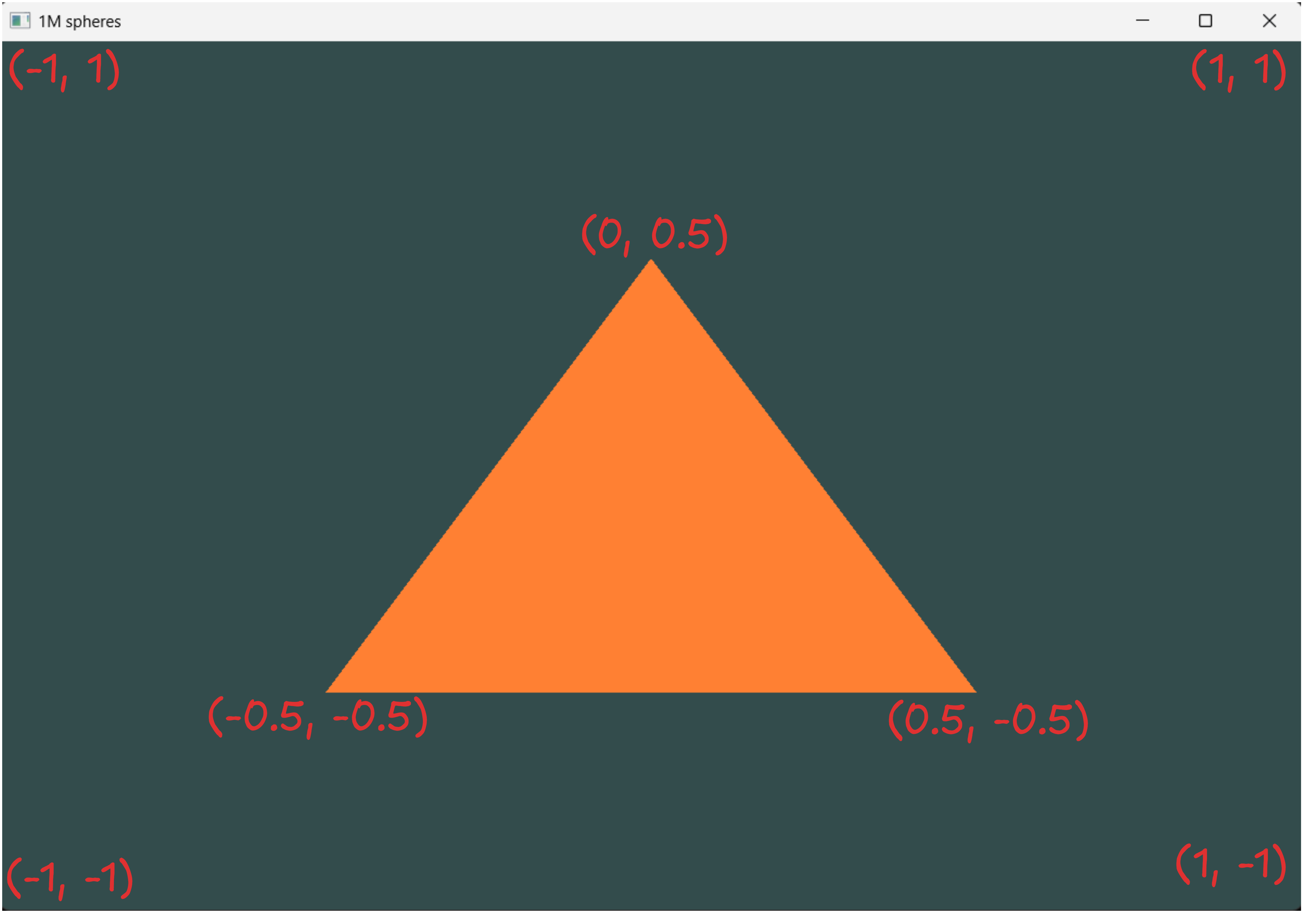 Here, z-coordinate is 0.0 because we are not passing any depth for now, to make it appear 2D.
Now, we need to pass this vertex data to our first stage of graphics pipeline which is vertex shader. For that, we need to create a memory buffer on the GPU which is named as Vertex Buffer Object (VBO). It can store a large number of vertices in its GPU memory, which gives us the advantage of sending large batches at once rather than one at a time. Since this data transfer between CPU and GPU is relatively slow, we’ll try to pass as much data as possible at once. Once it’s in GPU memory, it will be instantly accessible which makes it extremely fast. Remember this point, we’ll take advantage of this during our optimization phase for 1 Million spheres.
We can generate any buffer using glGenBuffers() and bind them to respective buffer type which is GL_ARRAY_BUFFER in this case using glBindBuffer().
GLuint VBO;
glGenBuffers(1, &VBO);
glBindBuffer(GL_ARRAY_BUFFER, VBO);
From this point, every buffer calls we make to the GL_ARRAY_BUFFER target will point to currently bound buffer which is VBO.
Now we’ll call glBufferData() to copy previously defined data of vertices into the currently bound buffer’s memory. The first argument we pass is the buffer type currently bound to the VBO. The second argument is the total size of data (in bytes) we are passing. The third parameter is the actual data we pass and the last parameter just defines how we want GPU to manage the provided data. Here, GL_STATIC_DRAW defines that this data will get set once and used many times.
glBufferData(GL_ARRAY_BUFFER, sizeof(vertices), vertices, GL_STATIC_DRAW);
Now we have our data inside the GPU memory, we will create vertex and fragment shader to process it.
Vertex Shader
Shaders can be written in GLSL (OpenGL Shading Language) and HLSL (High-Level Shading Language). For now, we will use GLSL. Here is a very basic vertex shader code that we will use for our program.
#version 330 core // declares the version
layout (location = 0) in vec3 aPos; // declaring input vertex attribute

void main() // declaring main function (same as C)
{
    gl_Position = vec4(aPos, 1.0); // setting gl_Position (the input for next stage) with aPos values
                //last parameter is w, which controls perspective division
}
Perspective division tells us how an object’s size decreases with increase in distance, similar to human’s perception. Here, we are setting it to 1.0 as it’s just 2D now.
For this simple program of just drawing a triangle, we will declare the vertex shader code in our main.cpp file only.
const char* vertexShaderSource = "#version 330 core\n"
    "layout (location = 0) in vec3 aPos;\n"
    "void main()\n"
    "{\n"
    "   gl_Position = vec4(aPos.x, aPos.y, aPos.z, 1.0);\n"
    "}\0";
For OpenGL to use this shader, it has to be dynamically compiled at run time. So we will create a shader object, attach the shader source code with this object and then compile it.
GLuint vertexShader = glCreateShader(GL_VERTEX_SHADER);
glShaderSource(vertexShader, 1, &vertexShaderSource, NULL); // 2nd argument here is the number of strings we are passing as source code
glCompileShader(vertexShader);
If you want, you can add a compilation check if its successful or not using glGetShaderiv().
GLint hasCompiled;
char infoLog[1024]; // to store the error msg
glGetShaderiv(shader, GL_COMPILE_STATUS, &hasCompiled);
if (hasCompiled == GL_FALSE)
{
    glGetShaderInfoLog(shader, 1024, NULL, infoLog);
    std::cout << "SHADER_COMPILATION_ERROR:\n" << infoLog << std::endl;
}
Fragment Shader
We will follow the same steps as for the vertex shader like first define the fragment shader source, then create an object for fragment shader and then compile it. But before that here is our fragment shader code in GLSL with commented details.
// GLSL code
#version 330 core // declares the version
out vec4 FragColor; // declaring output fragment color

void main() // declaring main function (same as C)
{
    FragColor = vec4(1.0f, 0.5f, 0.2f, 1.0f); // setting color of fragment
}
const char* fragmentShaderSource = "#version 330 core\n"
    "out vec4 FragColor;\n"
    "void main()\n"
    "{\n"
    "   FragColor = vec4(1.0f, 0.5f, 0.2f, 1.0f);\n"
    "}\0";

GLuint fragmentShader;
fragmentShader = glCreateShader(GL_FRAGMENT_SHADER);
glShaderSource(fragmentShader, 1, &fragmentShaderSource, NULL);
glCompileShader(fragmentShader);
Now that both shaders are compiled, we have to link both shader objects into a shader program.
Shader Program
A shader program object is the final linked version of all shaders combined (for now vertex and fragment shader only). We will follow a similar approach here too- first create a shader program object, attach both shaders and link them using glLinkProgram(). We can now activate this shader program using glUseProgram().
GLuint shaderProgram;
shaderProgram = glCreateProgram();
glAttachShader(shaderProgram, vertexShader); // output of this shader is input for next shader
glAttachShader(shaderProgram, fragmentShader); // output of previous shader is input to this shader
glLinkProgram(shaderProgram);

glUseProgram(shaderProgram);
After linking both shaders to shaderProgram we can delete both vertexShader and fragmentShader objects.
glDeleteShader(vertexShader);
glDeleteShader(fragmentShader);
So, the GPU have our data, it knows what to do with it but it doesn’t know how to interpret it.
Linking Vertex Attributes
Our Vertices[] array consists of 9 float variables but one vertex is defined by 3 float variables determining its position. Now we need to tell GPU that:
- for first vertex, start reading from 0th position in memory upto 3 * 4 byte (float size) = 12 bytes.
- for second vertex, read from (0 + 12)th byte to 12 + 12 = 24th byte.
- for third vertex, start reading from 24th byte for 12 bytes.
So, I hope you understand how this reading will take place when we will pass color, normals etc with this data. We can tell all this to OpenGL using glVertexAttribPointer().
glVertexAttribPointer(0, 3, GL_FLOAT, GL_FALSE, 3 * sizeof(float), (void*)0);
glEnableVertexAttribArray(0); // enables the vertex attribute of index 0
So, for glVertexAttribPointer the passed arguments defines following:
- First argument determines which vertex attribute we want to define. Here, it’s
aPoswithlayout (location = 0)which sets the location of this vertex attribute to 0 and we can pass data to this attribute using 0. - Second argument defines its size. Since, aPos is a vec3, it will take 3 values.
- Third argument specifies the data type
- Fourth argument specifies whether the data should be normalized (not needed here)
- The fifth argument defines stride that means after how much byte the next value of current attribute starts, which is 3 here (pos- x, y, z).
- The sixth argument is the offset which you can set if we are passing multiple properties at a time. Currently its aPos only so it’s (void*)0.
Vertex Array Object
We will need to create one more object which will keep all the states we need to supply vertex data which is our VBO. So when drawing multiple objects, we don’t need to configure VBO every single time before drawing. Just configure them once and bind them to a VAO, then just bind this VAO before drawing which requires just one function call.
We can generate a VAO using glGenVertexArrays().
unsigned int VAO;
glGenVertexArrays(1, &VAO);
Then we’ll bind this vertex array object, and configure our VBO, and finally we can unbind our VBO and VAO. Now when we want to draw anything, just before that again bind this VAO. That’s all we need to remember as a constant flow.
So, that’s all the setup we need and we are ready to draw our triangle. Inside our infinite while loop, activate the shaderProgram, bind the VAO and call glDrawArrays(GL_TRIANGLES, 0, 3) to draw triangle. The first argument to glDrawArrays specifies what to draw other options are GL_POINTS and GL_LINES. The second argument tells the starting index of vertex array and last argument specifies the number of vertices to draw.
glUseProgram(shaderProgram);
glBindVertexArray(VAO);
glDrawArrays(GL_TRIANGLES, 0, 3);
So, output of all this is the same image but without my coordinates marking.
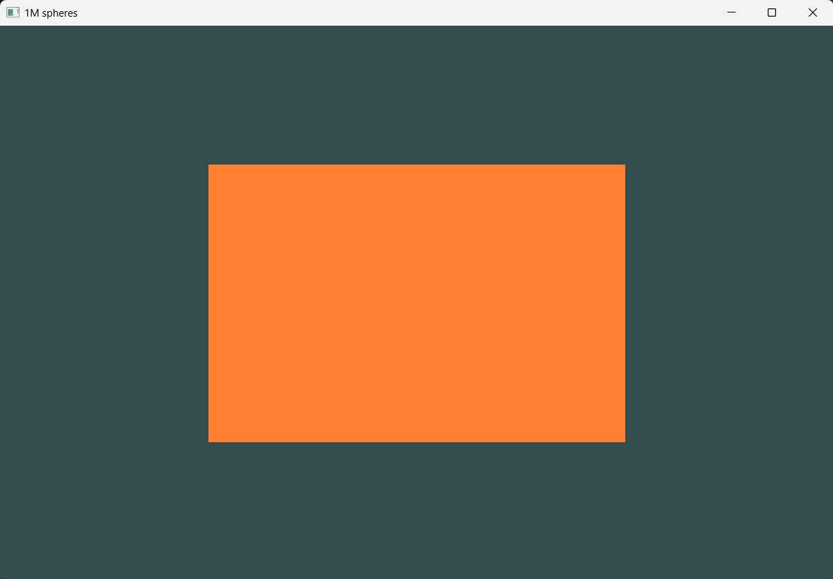
Element Buffer Objects
Let’s suppose we want to draw multiple triangles and they are connected as such most of these triangles share common vertices. Then it’s not a good idea to define vertices of all these triangles one by one. It’s better to define all the vertices of the polygon and then define the traingle vertices using their index sequence.
I’ll explain this by drawing a rectangle. So, if we use the VBO method we need to define 6 vertices (3 for each triangle) like this
float vertices[] = {
    0.5f,  0.5f, 0.0f,
    0.5f, -0.5f, 0.0f,
    -0.5f,  0.5f, 0.0f,

    0.5f, -0.5f, 0.0f,
    -0.5f, -0.5f, 0.0f,
    -0.5f,  0.5f, 0.0f
};

// and use 6 vertices for glDrawArrays
glDrawArrays(GL_TRIANGLES, 0, 6);
But with EBO, we just need to declare all our unique triangle vertices and then create another array which will determine the sequence of those vertices to form a triangle.
float vertices[] = {
    0.5f,  0.5f, 0.0f,
    0.5f, -0.5f, 0.0f,
    -0.5f, -0.5f, 0.0f,
    -0.5f,  0.5f, 0.0f
};
unsigned int indices[] = {
    0, 1, 3,   // first triangle
    1, 2, 3    // second triangle
};
Then we declare the EBO after binding the VAO, so the VAO will store the EBO’s state. We then call glDrawElements() instead of glDrawArrays();
GLuint EBO;
glGenBuffers(1, &EBO);
glBindBuffer(GL_ELEMENT_ARRAY_BUFFER, EBO);
glBufferData(GL_ELEMENT_ARRAY_BUFFER, sizeof(indices), indices, GL_STATIC_DRAW);
...
...
while(true){
    ...
    ...
    glDrawElements(GL_TRIANGLES, 6, GL_UNSIGNED_INT, 0); // 2nd argument is number of indices, 3rd is type of indices, last is just offset
    ...
    ...
}
Our output looks like this now.
So, we have covered a lot up to this point, providing fundamental knowledge for rendering a single sphere and, later, 1 million spheres.
In the next post, I’ll try to cover everything we need to understand 3D in OpenGL.