Rendering 1 Million spheres: Part 2 (3D basics with OpenGL)
This post is a continuation of my previous post which is the first part of this series. In this blog, we will cover the textures, 3D basics including lighting and the camera.
But before we start, I want to modularize our existing codeto follow the OOP principles.
Code Refactoring
o far, we’ve been using VBO, VAO, EBO and Shaders. So, we’ll create classes for all these objects. Then we’ll create a common Mesh class to encapsulate all these Buffer objects together.
For Buffer objects, we mainly need a single unsigned integer variable to reference it, a Bind function, an Unbind function and a Delete function for cleanup.
class VBO
{
public:
	// Reference ID of the Buffer Object
	GLuint ID;
	// Constructor that generates a Buffer Object and binds it to some data
	VBO(...);

	void Bind() const; // call glBindBuffer(GL_ARRAY_BUFFER, ID);
	void Unbind(); // call glBindBuffer(GL_ARRAY_BUFFER, 0);
	void Delete() const; // call glDeleteBuffers(1, &ID);
};
In the case of VAO, we also need an extra function to link a VBO attribute to the VAO.
void VAO::LinkAttrib(VBO& VBO, GLuint layout, GLuint numComponents, GLenum type, GLsizeiptr stride, void* offset){
    VBO.Bind();
    glVertexAttribPointer(layout, numComponents, type, GL_FALSE, stride, offset);
    glEnableVertexAttribArray(layout);
    VBO.Unbind();
}
Now, we need to create a Shader class to handle vertex and fragment shader objects creation, their compilation, followed by creation and linking of the shader program object. We also need to handle shader activation.
std::string get_file_contents(const char* filename); // reads the file and returns its content in string

class Shader {
public:
	GLuint ID;
	std::string shaderName;
	Shader(const char* vertexFilePath, const char* fragmentFilePath, const char* shaderName);

	void Activate() const;
	void Delete() const;
private:
	void compileErrors(unsigned int shader, const char* type);
};
We can create ShaderClass object like
Shader sphereShader("./sphere.vert", "./sphere_pbr.frag", "PBR");
We also have to create a Mesh class which will combine all this.
class Mesh {
public:
    std::vector <glm::vec3> vertices;
    std::vector <GLuint> indices;

    VAO mainVAO;

	Mesh(std::vector <glm::vec3>& vertices, std::vector <GLuint>& indices);

    void Draw(Shader& shader);
}
I’ll also define Mesh() and Draw() functions just for your reference.
// Mesh.cpp file
Mesh::Mesh(std::vector<glm::vec3>& vertices, std::vector<GLuint>& indices) // Constructor for Mesh class
{
    Mesh::vertices = vertices;
    Mesh::indices = indices;

    mainVAO.Bind();
    VBO mainVBO(vertices);
    EBO mainEBO(indices);
    mainVAO.LinkAttrib(mainVBO, 0, 3, GL_FLOAT, sizeof(glm::vec3), (void*)(0));
    mainVAO.Unbind();

    mainVBO.Unbind();
    mainEBO.Unbind();
}

void Mesh::Draw(Shader& shader) // Draw function for Mesh Object
{
    shader.Activate();
    mainVAO.Bind();

    glDrawElements(GL_TRIANGLES, indices.size(), GL_UNSIGNED_INT, 0);
}
So, we will initialize a Mesh rectangle like
std::vector<glm::vec3> vertices = {
    glm::vec3(0.5f,  0.5f, 0.0f),
    glm::vec3(0.5f, -0.5f, 0.0f),
    glm::vec3(-0.5f, -0.5f, 0.0f),
    glm::vec3(-0.5f,  0.5f, 0.0f)
};
std::vector<GLuint> indices = {
    0, 1, 3,   // first triangle
    1, 2, 3    // second triangle
};
Mesh rectangle(vertices, indices);
...
...
while(true){
    ...
    ...
    rectangle.Draw(sampleShader);
    ...
    ...
}
Todo: Add link to source code
Some more basics of Shaders
Till now we have seen how to pass data to vertex shader. To pass data from vertex shader to fragment shader, we need to declare a variable in vertex shader with out and then redeclare it with same name in fragment shader but with in.
// inside vertex shader
out vec4 color;

// inside fragment shader
in vec4 color;
There is one more way to pass data to shaders and that is Uniforms. But they work a little differently as they are global for a particular shader progrma, can be accessed in both vertex and fragment shaders, and can be accessed or updated at any stage of the application.
We can declare them using the uniform keyword, for example: uniform vec4 color;
To set their values from OpenGL, we need to use specific functions based on the data type. It’s better to add these functions directly inside our Shader class.
void setBool(const std::string &name, bool value) const
{
    glUniform1i(glGetUniformLocation(ID, name.c_str()), (int)value);
}
void setInt(const std::string &name, int value) const
{
    glUniform1i(glGetUniformLocation(ID, name.c_str()), value); // glUniform1i for integer
}
void setFloat(const std::string &name, float value) const
{
    glUniform1f(glGetUniformLocation(ID, name.c_str()), value); // glUniform1f for float
}
// glUniform1fv: for a float vector/array.
// glUniform4f : for 4 floats.
Textures
Textures can be understood as 2D images which we can mapped over our 3D object. Till now we were filling a color over an object by directly passing the RGB values but now we will sample them from a texture and apply the resulting RGB values to that object.
But for that we need to define which part of texture (texture coordinate) maps to which vertex. Each vertex should have a texture coordinate associated with it. Texture coordinates have range between 0 and 1 in both x and y axis. The retrieval of texture color using texture coordinates is defined as Sampling.
Generally, we define our texture coordinates in between range of 0 and 1, to completely wrap the texture over the object. But if we define them outside of this range of 0 and 1, by default, they will start repeating. Suppose we define them between 0 and 5, the texture will repeat for five times by default but we can also assign different behaviors like mirrored repeat, clamp to border and clamp to edge.
We can assign all these properties using glTexParameteri().
For texture filtering, we have two options like GL_NEAREST and GL_LINEAR. GL_NEAREST is default texture filtering method which results in blocky pattern and will clearly define the edges while GL_LINEAR gives a smooth pattern for edges. We will decide what to use will totally depend on our requirement.
Generally, we typically set it such that when scaling up (magnifying), use GL_LINEAR and for downscaled texture use GL_NEAREST.
We also have option to create mipmaps, which allows us to create different texture versions for different resolutions (always of lesser resolutions). It enables us to not use a large resolution texture for the objects which are far from our camera. It will also help in improving the performance.
Creating a Texture
To upload an image for generating a texture, we will use a library called stb_image.h. You can download it from here and then save it to your project. Then create a new cpp file named stb.cpp and include the following code:
#define STB_IMAGE_IMPLEMENTATION
#include "stb_image.h"
Now we will start by creating a Texture class for our application including standard Bind, Unbind and Delete function. We also need to bind our texture to a shader, for that we’ll create one more function.
class Texture {
public:
	GLuint ID = 0;

	Texture(const char* image, GLenum slot, GLenum format, GLenum pixelType);

	// Assigns a texture unit to a Shader
	void texUnit(Shader& shader, const char* uniform, GLuint unit);
	// Binds a texture
	void Bind() const;
	// Unbinds a texture
	void Unbind();
	// Deletes a texture
	void Delete() const;
};
We will declare our Texture constructor such that it will load our image and generate and configure a texture. Textures are generated with glTexImage2D() and we need to pass following parameters to it.
- First argument - texture target, which is
GL_TEXTURE_2Dfor now - Second arg - the mipmap level, for which we want to generate this texture
- Third arg - the format in which we want to save the texture on GPU, it’s
RGBbecause our image contains that data only - Fourth and Fifth argument defines the width and height
- Sixth argument will always be 0.
- The seventh argument specifies the format (e.g.,
GL_RGB) and the data type (e.g.,GL_UNSIGNED_BYTE) of the source image data. - The eighth argument is a pointer to the image data.
Texture::Texture(const char* imagePath, GLenum slot, GLenum format, GLenum pixelType)
{
	int widthImg, heightImg, numColCh;
	stbi_set_flip_vertically_on_load(true);
	unsigned char* bytes = stbi_load(imagePath, &widthImg, &heightImg, &numColCh, 0);
	if (!bytes) {
		std::cerr << "Failed to load HDR texture at path: " << imagePath << std::endl;
		return;
	}
	else {
		std::cout << imagePath << " loaded correctly.\n";
	}
    // genearating and binding texture
	glGenTextures(1, &ID); // first argument is the number of textures we want to generate, 2nd arg is the address where we want to store them
	glBindTexture(GL_TEXTURE_2D, ID);

    //setting parameters
	glTexParameteri(GL_TEXTURE_2D, GL_TEXTURE_MIN_FILTER, GL_LINEAR_MIPMAP_LINEAR);
	glTexParameteri(GL_TEXTURE_2D, GL_TEXTURE_MAG_FILTER, GL_LINEAR);

	glTexParameteri(GL_TEXTURE_2D, GL_TEXTURE_WRAP_S, GL_MIRRORED_REPEAT);
	glTexParameteri(GL_TEXTURE_2D, GL_TEXTURE_WRAP_T, GL_REPEAT);

	glTexImage2D(GL_TEXTURE_2D, 0, GL_RGBA, widthImg, heightImg, 0, format, pixelType, bytes);
	glGenerateMipmap(GL_TEXTURE_2D);

	stbi_image_free(bytes);
	glBindTexture(GL_TEXTURE_2D, 0); // unbinding
}
...
void Texture::texUnit(Shader& shader, const char* uniform, GLuint unit)
{
	GLuint uniTex0 = glGetUniformLocation(shader.ID, uniform);
	shader.Activate();
	glUniform1i(uniTex0, unit);
}
Applying Textures
We will pass the texture coordinates like following
std::vector<glm::vec2> texCoords = {
    glm::vec2(0.0f, 0.0f),
    glm::vec2(1.0f, 0.0f),
    glm::vec2(0.0f, 1.0f),
    glm::vec2(1.0f, 1.0f)
};
Then we need to pass these coordinates to the shader code too. For that we need to create a new VBO and add a constructor that supports glm::vec2, bind it to the pre existing VAO and finally link it.
mainVAO.LinkAttrib(texCoordVBO, 1, 2, GL_FLOAT, sizeof(glm::vec2), (void*)(0));
In the shader side, we need to define a layout with location = 1 for texture Coordinates and pass this data to the fragment shader via an out variable in the vertex shader and in variable in the fragment shader. In fragment shader, we will assign FragColor with texture () function provided by GLSL, in which we need to pass texture sampler and texture coordinates. This texture() function returns the color sampled from the texture at the given coordinates.
// In vertex shader
layout (location = 1) in vec2 aTexCoord;
out vec2 TexCoord;
void main(){
    ...
    TexCoord = aTexCoord;
    ...
}
// in fragment shader
in vec2 TexCoord;

uniform sampler2D sampleTexture;
void main()
{
    FragColor = texture(sampleTexture, TexCoord);
}
Finally, activate and bind the texture, then set the uniform sampler (e.g., sampleTexture) in your shader program..
glActiveTexture(GL_TEXTURE0);
glBindTexture(GL_TEXTURE_2D, myTexture.ID);

//for setting the texture in shader
mytexture.texUnit(sphereShader, "sampleTexture", 0);
At this point, you should be able to see the texture drawn on your rectangle.
Different Coordinates systems
In 3D graphics, we usually define object coordinates in world space, where positions can theoretically range from −INF to +INF in all three directions. However, the Normalized Device Coordinates (NDC) - the final coordinates used to render on the screen - ranges from -1.0 to 1.0 in both the X and Y axes of screen.
To transform object coordinates from their local origin to NDC, they pass through the following five coordinate systems:
- Local/Model space - Local space defines the coordinates space which is local to our object. For example, the origin
(0,0,0)is often placed at the center of the object, but it can be at a corner if needed (e.g., for rotating around a corner). Transformations likescaling,rotation, andtranslationare applied here using a model matrix. This matrix encodes how the object should be positioned and oriented in the world space. - World/Global space - World space places all objects in a common 3D environment. When we load multiple objects, they initially appear at the world origin (0,0,0), but we typically reposition them using world-space transformations. Changes in world space (e.g., moving or rotating the object) do not affect the local properties of the object. So, if we have two instances of the same object, world-space transformations applied to one will not impact the other.
- View/Camera/Eye space - This space represents what the camera sees. A view matrix transforms world-space coordinates into camera-space coordinates, placing the camera at the origin and rotating/transforming everything relative to it.
This transformation ensures that only objects within the camera’s field of view are considered for rendering. We’ll discuss more about it in the
Camerasection. - Clip space - As we want our final coordinates in between -1.0 and 1.0, we will use a projection matrix that specifies a range of coordinates in each direction, and the objects lying outside this range will not be clipped and mapped in between -1.0 and 1.0 . The projection matrix transforms view-space coordinates into clip space. If we visualize this projection matrix, it will look like a 3d container or frustum, which will hold the objects inside and whatever is outside of it, will not be rendered on the screen. This projection matrix converts 3d coordinates to device coordinates which can be mapped to NDC.
- Screen space - In last, the clip space coordinates will be converted to screen space coorinates using viewport transform. The coordinates of range -1.0 and 1.0 will changed to the range define by glViewport i.e. 0 to WIDTH in x-axis and 0 to HEIGHT in y-axis.
So, finally a coordinate in clip space will get transformed as
\[V_{clip} = M_{projection} \cdot M_{view} \cdot M_{model} \cdot V_{local}\]Camera
To define a camera in 3D space, we simulate its behavior by transforming the world relative to the camera. This transformation is represented by the view matrix. To compute it, we need a few important vectors:
- Position vector - It defines the current position of our camera in world space,
(x, y, z). - Direction vector - It defines the direction the camera is looking. It is calculated by subtracting the camera’s position and target Position, and then normalizing it.
glm::vec3 cameraDirection = glm::normalize(cameraPos - cameraTarget); - Up axis - It tell the
updirection for camera space. As we are taking theupdirection in y-axis, it will be (0, 1, 0);glm::vec3 Up = glm::vec3(0.0f, 1.0f, 0.0f); - Right axis - It represent the positive x-axis of camera space. We can calculate it by doing a cross product between Up vector and Camera Direction vector, it will result in a perpendicular vector to both.
glm::vec3 RightDir = glm::normalize(glm::cross(Orientation, Up));
Now we need to define two matrices, view and projection matrix, which helps us convert world coordinates to clip space coordinates.
The View matrix can be calculated by using glm::lookAt(position, target, Up) function.
The projection matrix can be defined in two ways as we have two different types of camera systems - perspective camera (how humans perceive the world) and orthographic camera(where all objects appear the same size regardless of distance).
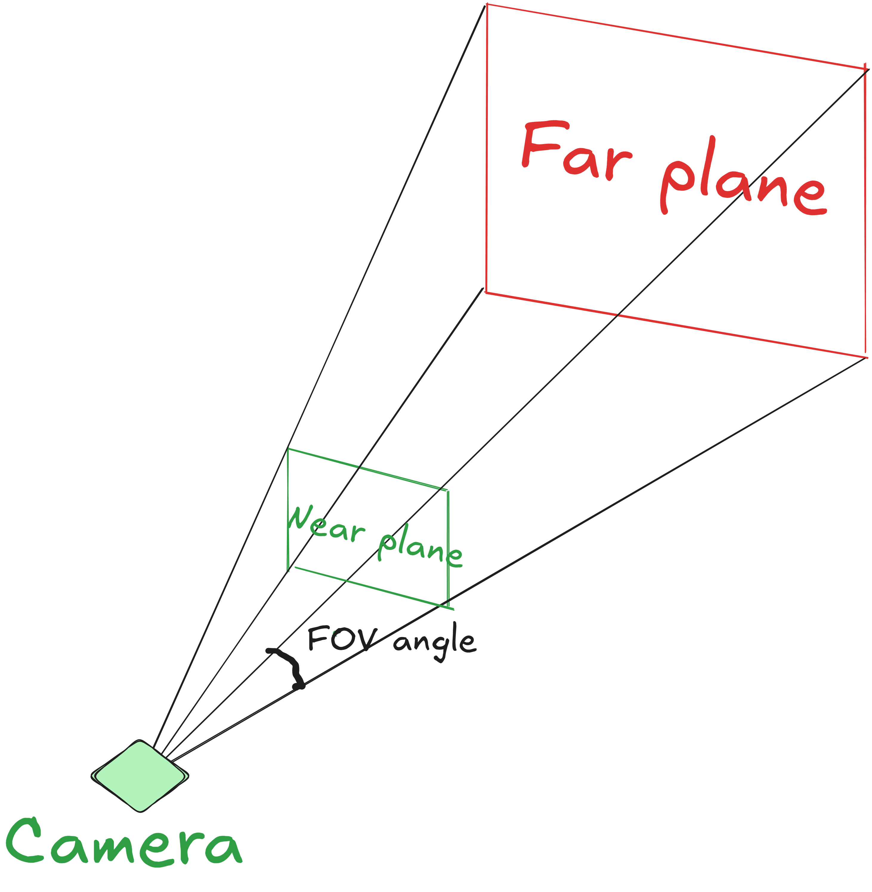
- Perspective projection - Perspective projection is very similar to how humans perceive the world like distant objects will look smaller than the near objects. We will also try to convert our world space coordinates in such a way that it will produce the same result. If you remember we had a
wparameter fromgl_Position, it will increase with the distance from the camera and then the (x, y, z) coordinates will be divided by their corresponding w value, which will result in NDC. A perspective matrix can be defined usingglm::perspective(FOVangle, aspectRatio, near, far). We can visualize a perspective frustum like the following diagram:
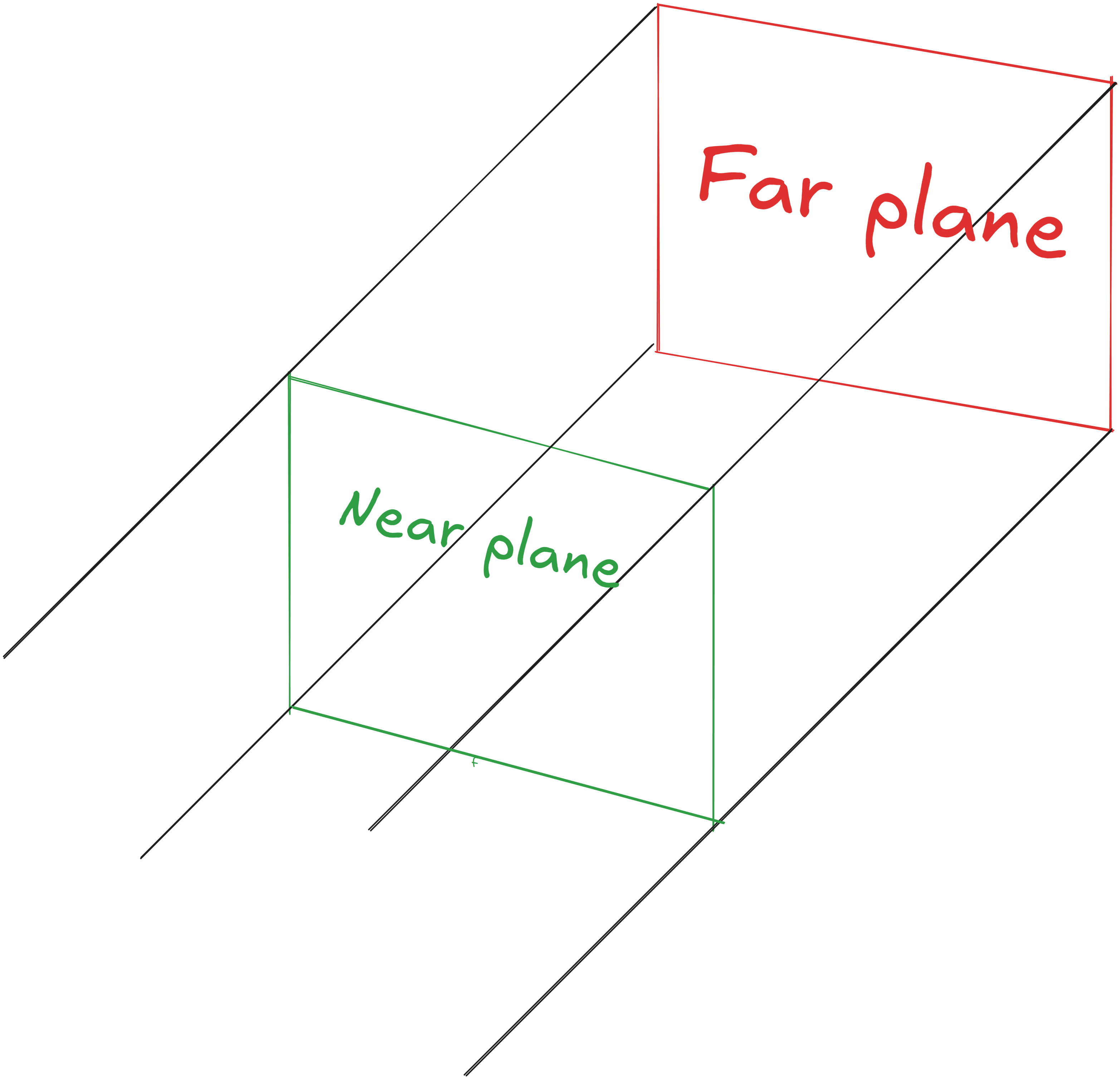
- Orthographic projection - Orthographic projection is just like where all objects appear the same size regardless of distance. In this case, the w value will always be 1.0. It can be defined using
glm::ortho(left, right, bottom, top, near, far);. We can visualize an orthographic frustum like following image:
Before starting to use the camera, We’ll create a Camera class which has functions to support handling inputs for camera movement and updating the viewProjection/camera matrix for shader.
class Camera {
public:
	glm::vec3 Position = glm::vec3(0.0f, 0.0f, 10.0f);
	glm::vec3 Orientation = glm::vec3(0.0f, 0.0f, -1.0f);
	glm::vec3 Up = glm::vec3(0.0f, 1.0f, 0.0f);
	glm::vec3 RightDir = glm::normalize(glm::cross(Orientation, Up));

	glm::mat4 view;
	glm::mat4 projection;
	glm::mat4 cameraMatrix = glm::mat4(1.0f);

	int width;
	int height;

	Camera(int width, int height, glm::vec3 position);

	// Updates the camera(viewProjection) matrix for the Vertex Shader
	void updateMatrix(float FOVdeg, float nearPlane, float farPlane);
	// Exports the camera matrix to a shader
	void Matrix(Shader& shader, const char* uniform);
	// Handles camera inputs
	void Inputs(GLFWwindow* window);
};
We can update cameraMatrix in updateMatrix() function and handle keyboard inputs for camera movement in Inputs function.
void Camera::updateMatrix(float FOVdeg, float nearPlane, float farPlane)
{
	// Initializes matrices since otherwise they will be the null matrix
	view = glm::mat4(1.0f);
	projection = glm::mat4(1.0f);

	// Makes camera look in the right direction from the right position
	view = glm::lookAt(Position, Position + Orientation, Up); //Position + orientation will give the direction
	// Adds perspective to the scene
	projection = glm::perspective(glm::radians(FOVdeg), (float)width / height, nearPlane, farPlane); // using a perspective camera

	// Sets new camera matrix
	cameraMatrix = projection * view;
}
void Camera::Inputs(GLFWwindow* window)
{
	if (glfwGetKey(window, GLFW_KEY_W) == GLFW_PRESS)
	{
		Position += speed * Orientation; // changes position in the orientation (inside screen, -z axis) direction
	}
	if (glfwGetKey(window, GLFW_KEY_A) == GLFW_PRESS)
	{
		Position += speed * -glm::normalize(glm::cross(Orientation, Up)); // changes position in the left (-x axis) direction
	}
	if (glfwGetKey(window, GLFW_KEY_S) == GLFW_PRESS)
	{
		Position += speed * -Orientation;  // changes position in the opposite (out of screen) orientation (z axis) direction
	}
	if (glfwGetKey(window, GLFW_KEY_D) == GLFW_PRESS)
	{
		Position += speed * glm::normalize(glm::cross(Orientation, Up)); // changes position in the right (x axis) direction
	}
	if (glfwGetKey(window, GLFW_KEY_SPACE) == GLFW_PRESS)
	{
		Position += speed * Up;  // change position in the Up (y axis) direction
	}
	if (glfwGetKey(window, GLFW_KEY_LEFT_CONTROL) == GLFW_PRESS)
	{
		Position += speed * -Up; // change position in the Down (-y axis) direction
	}
}
We also have to set this new cameraMatrix as a uniform in the vertex shader using Matrix function.
void Camera::Matrix(Shader& shader, const char* uniform)
{
	glUniformMatrix4fv(glGetUniformLocation(shader.ID, uniform), 1, GL_FALSE, glm::value_ptr(cameraMatrix));
}
We also need to do some changes in our existing shader code to properly use the camera functionality in our application.
// Vertex shader
// add 2 extra uniforms
uniform mat4 camMatrix;
uniform mat4 model;
...
void main(){
    ...
	vec3 currPos = vec3(model * vec4(aPos, 1.0f));
    gl_Position = camMatrix * vec4(currPos, 1.0);
}
Lastly, call Input and updateMatrix function inside your rendering while loop.
while(true){
    ...
    camera.Inputs(window);
    camera.updateMatrix(45.0f, 0.1f, 300.0f);
    ...
}
// Inside Mesh::Draw function
void Mesh::Draw(Shader& shader, Camera& camera){
    shader.Activate();
    ...
    camera.Matrix(shader, "camMatrix");
    ...
}
Now you should be able to move in the scene with camera.
So, we’re done with the 3D basics - we mainly covered different coordinate systems and the camera. Lighting is left, but I won’t cover it in this blog; I’ll go through it later when we dive into PBR.
In the next blog, I’ll cover how to render circles and spheres, and explore how to start scaling them to 1 Million without performing any indirect optimization.