Rendering 1 Million spheres: Part 3 (Circle, Sphere and Spheres)
Circle
Before we start with spheres, I want to show how we can draw a circle. The easiest way to draw a circle is to draw multiple triangles and arrange them in a circular manner, just like in the following image:
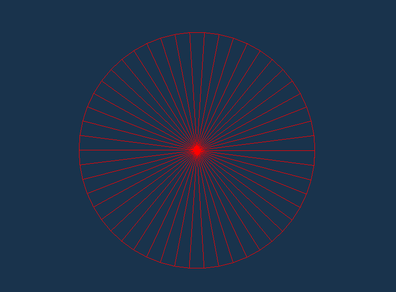
To arrange these triangles in such a manner that it will form a circle, we need to find the vertex positions accordingly. We will use mathematical equations to find them. If we plot our 2D circle on a XY plane, any point on the perimeter of circle can be calculated using some basic trigonometry.
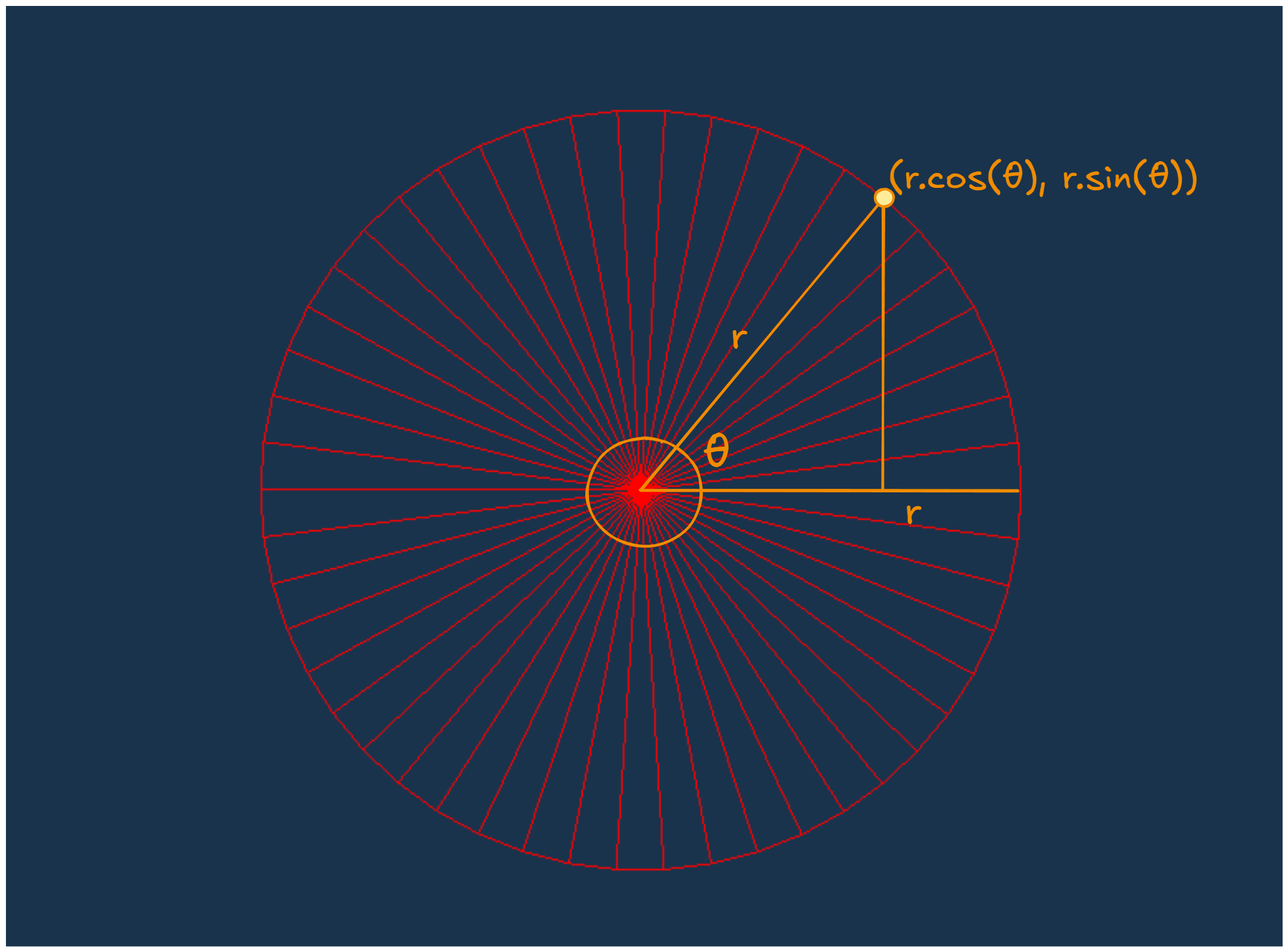
Now we know how to find all vertex positions in the circle, we just need to figure out how to arrange them in the indices array. For that, just visualize we are drawing all triangles by ourselves, then how would you do it. I’ll start from the center of the circle, then move to the second vertex $(r.cos(θ), r.sin(θ))$ and then to the third and last vertex of our triangle $(r.cos(θ+Δθ), r.sin(θ+Δθ))$. We will repeat it for whole 360° while Δθ is the angular step size of each segment. We can define the number of segments as we want but just remember with a high number of segments, the circle will be smoother but the number of vertices will also increase.
vector<glm::vec3> circleVertices;
vector<GLuint> circleInd;

const int numOfSegments = 50;
const float radius = 0.5f;

circleVertices.push_back(glm::vec3(0.0f, 0.0f, 0.0f));
for (int i = 0; i <= numOfSegments; i++) {
	float angle = 2.0f * 3.14f * (i / numOfSegments);
	float x = radius * cos(angle);
	float y = radius * sin(angle);
	circleVertices.push_back(glm::vec3(x, y, 0.0f));
}

for (int i = 1; i <= numOfSegments; ++i) {
	circleInd.push_back(0);        // Circle Center vertex
	circleInd.push_back(i);        // Current vertex
	circleInd.push_back(i + 1);    // Next vertex
}

circleInd.push_back(0);            // Center vertex
circleInd.push_back(numOfSegments); // Last vertex
circleInd.push_back(1);           // Closing the circle

Mesh circle(circleVertices, circleInd);
Before we start drawing it, we’ll also need to create a simple Model matrix for the circle and assign it in shader uniform, so it can interact properly with the camera.
glm::vec3 circlePos = glm::vec3(0.0f, 0.0f, 0.0f);
glm::mat4 circleModel = glm::mat4(1.0f); // an Indentity matrix with no translations, no rotations and no scaling
circleModel = glm::translate(circleModel, circlePos); // it will translate the model with circlePos, last column will contain circlePos (x, y, z), visulally it will shift the model to this circlePos
glUniformMatrix4fv(glGetUniformLocation(shaderProgram.ID, "model"), 1, GL_FALSE, glm::value_ptr(circleModel));
Now just call circle.Draw(shader, camera) inside rendering loop and run your application. It should render the circle like the following image.

Sphere
Next we need to render a Sphere. We will follow the same steps as above. But first we need to figure out how to calculate the vertex positions and then how to arrange them so that the triangles will form a spherical surface. Before we start, I want to clarify that we are going to draw triangles over the surface only, not inside. It will be a hollow sphere with triangles covering its surface.
We can calculate the vertices by visualizing a sphere in the following way.
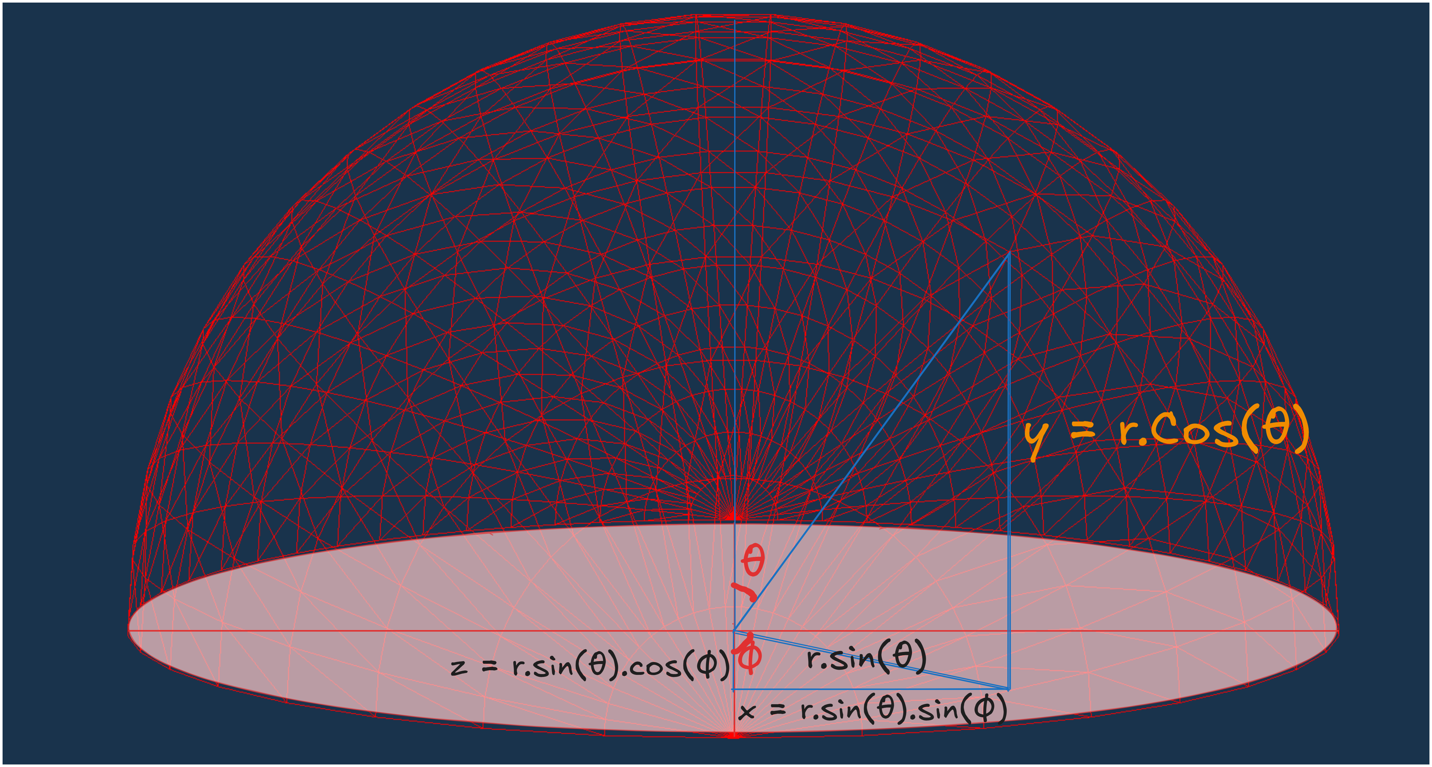
In the above image, first assume there is a line from the center to a vertex point. Now, $\theta$ is the angle between y-axis and that virtual line. So, the y-value for that vertex will be $r.cos(\theta)$. Then, if we draw the $sin(\theta)$ component of that line - it will lie on the xz-plane and $\phi$ will be the angle between this line and z-axis. So, the z-value will be $r.sin(\theta).cos(\phi)$ and the x-value will be $r.sin(\theta).sin(\phi)$.
\[\begin{align*} x &= r \cdot sin(\theta) \cdot sin(\phi) \\ y &= r \cdot cos(\theta)\\ z &= r \cdot sin(\theta) \cdot cos(\phi) \\ \end{align*}\]This way we will define all our vertex positions and push them into the indices array, just think of it as a sphere grid and traverse it row(level) wise.
vector<glm::vec3> sphereVertices;
vector<GLuint> sphereIndices;

const int latitudeSegments = 25;  // Number of vertical divisions
const int longitudeSegments = 25; // Number of horizontal divisions
const float radius = 2.5f;

for (int i = 0; i <= latitudeSegments; ++i) {
	float theta = i * 3.14159265359f / latitudeSegments; // Polar angle (0 to π), we only need to cover the half part because other half will be covered becuase of whole traversal in horizontal cut
	for (int j = 0; j <= longitudeSegments; ++j) {
		float phi = j * 2.0f * 3.14159265359f / longitudeSegments; // Azimuthal angle (0 to 2π)
		// Vertex position
		float x = (radius) * sin(theta) * sin(phi);
		float y = (radius) * cos(theta);
		float z = (radius) * sin(theta) * cos(phi);

		sphereVertices.push_back(glm::vec3(x, y, z));
	}
}
for (int i = 0; i < latitudeSegments; ++i) {
	for (int j = 0; j < longitudeSegments; ++j) {
		// Calculate indices for two triangles per grid cell
        // i defining the vertical level starting from top
        // j tells the horizontal level but it traverse it in a circluar way
		unsigned int first = (i * (longitudeSegments + 1)) + j; // index of the current vertex in the sphere grid
		unsigned int second = first + longitudeSegments + 1;    // index of the vertex directly below the current vertex

		sphereIndices.push_back(first);         // Current vertex
		sphereIndices.push_back(second);        // Vertex directly below
		sphereIndices.push_back(first + 1);     // Vertex in the right

		sphereIndices.push_back(second);        // Vertex directly below
		sphereIndices.push_back(second + 1);    // Vertex below and to the right
		sphereIndices.push_back(first + 1);     // Vertex in the right
	}
}

Mesh sphere(sphereVertices, sphereIndices);
Then set the sphere model matrix in the shader and call Draw() inside the rendering loop. We don’t need to change anything in the shader code.
...
glm::vec3 spherePos = glm::vec3(0.0f, 0.0f, 0.0f);
glm::mat4 sphereModel = glm::mat4(1.0f);
sphereModel = glm::translate(sphereModel, spherePos);
glUniformMatrix4fv(glGetUniformLocation(shaderProgram.ID, "model"), 1, GL_FALSE, glm::value_ptr(sphereModel));
...
sphere.Draw(shaderProgram, camera);
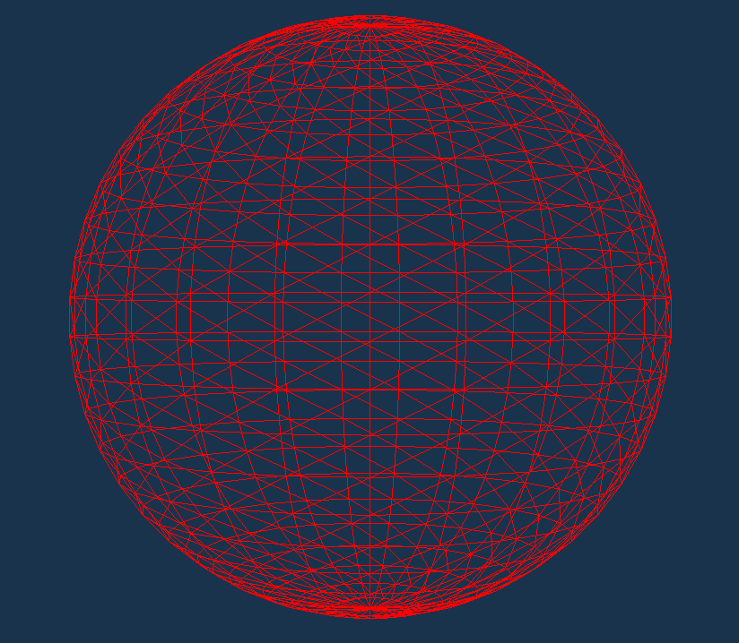
Now, we are done with rendering a sphere but you may not be able to recognize it as a sphere because we have not enabled normals and lighting yet. So, to visualize it enable glPolygonMode, which will just draw the triangle without filling them with colors.
glPolygonMode(GL_FRONT_AND_BACK, GL_LINE);
Spheres
Now that we know how to draw a Sphere, we will try to scale it.
So, the first approach we can follow is very simple and direct, just create an array to store the vertices vector<vector<glm::vec3>> baseSphereVertices; and for indices we can use the same indices array. Then create an array of objects of Mesh class vector<Mesh>spheres and create multiple objects of Mesh class with these different vertices and indices and push_back them to spheres array.
vector<Mesh>spheres;
Mesh baseSphere(baseSphereVertices, baseSphereInd);
spheres.push_back(baseSphere);
Now, inside rendering loop, run another for loop to draw each sphere.
This approach will work for some 1000s spheres but after that it will stop working smoothly and fps (from 60 fps) will drop with delayed update on screen. For my machine, it went well till some 1.5k spheres and after that fps started dropping.
So what’s the next thing we can do to improve the performance with more number of spheres. We can use some direct and indirect methods like decreasing the data transfer between CPU and GPU, reducing the nummber of Draw calls to GPU.
Currently inside our Draw() function, we are calling glDrawElements which draws a single sphere. So, when we call this Draw funtion for 1000 times, it calls 1000 draw calls to the GPU which is a very expensive operation.
But OpenGL provides a very useful function glDrawElementsInstanced, which allow us to draw same type of Mesh, n number of times with improved performance.
glDrawElementsInstanced(GL_TRIANGLES, indices.size(), GL_UNSIGNED_INT, 0, numInstances); // numInstances tells the number of times we want to draw a Mesh
But before we can use it, we need to setup some things. Till now we were passing all of the vertices for each sphere to the GPU, instead of this we will pass the vertices of 1 sphere and then only pass the origin center of all other spheres and inside our shader code only we will calculate the position of the other sphere vertices by translating the baseSphere vertices to current sphere origin point. This way we will improve our performance as we have shifted our calculation part of sphere vertices to GPU which can run thousands of calculations parallely. We also need to create a new Mesh Contructor with new InstanceVBO class, which is similar to VBO class. It will modularize our code and we need a different function for linking instance VBOs to our VAO.
// VAO.cpp
void VAO::LinkAttrib(InstanceVBO& instanceVBO, GLuint layout, GLuint numComponents, GLenum type, GLsizeiptr stride, void* offset) const
{
	instanceVBO.Bind();
	glEnableVertexAttribArray(layout);
	glVertexAttribPointer(layout, numComponents, type, GL_FALSE, stride, offset);
	glVertexAttribDivisor(layout, 1); // the rate at which vertex attribute will advance per instance
	instanceVBO.Unbind();
}
// Mesh.cpp
Mesh::Mesh(std::vector<Vertex>& vertices, std::vector<GLuint>& indices, std::vector<glm::vec3> &instancePositions)
{
	Mesh::vertices = vertices;
	Mesh::indices = indices;
	Mesh::instancePositions = instancePositions;

	mainVAO.Bind();

	VBO mainVBO(vertices);
	EBO mainEBO(indices);
	InstanceVBO instanceVBO(instancePositions);

	mainVAO.LinkAttrib(VBO, 0, 3, GL_FLOAT, sizeof(glm::vec3), (void*)0);

	mainVAO.LinkAttrib(instanceVBO, 1, 3, GL_FLOAT, sizeof(glm::vec3), (void*)(0));

	mainVAO.Unbind();
	mainVBO.Unbind();
	mainEBO.Unbind();
	instanceVBO.Unbind();
}
...
// new Draw function calling glDrawElementsInstanced
void Mesh::Draw(Shader& shader, Camera& camera, GLsizei numInstances){
    shader.Activate();
	VAO.Bind();

	camera.Matrix(shader, "camMatrix");

	glDrawElementsInstanced(GL_TRIANGLES, indices.size(), GL_UNSIGNED_INT, 0, numInstances);
}
We also need to do some changes in our vertex shader code to include instancePositions.
...
layout (location = 1) in vec3 instancePos;
...
gl_Position = camMatrix * vec4(currPos + instancePos, 1.0); // shifting each vertex with instancePosition
// Main.cpp
std::vector<glm::vec3> instancePositions;
int numInstances = 25000; // For my machine, it worked good till ~25k spheres, after that frame drop
instancePositions.resize(numInstances);

for (int i = 0; i < numInstances; ++i) {
	glm::vec3 position(
		dis2(gen), dis2(gen), dis2(gen)
	);
	instancePositions[i] = position;
}
...
Mesh baseSphere(sphereVertices, sphereIndices, instancePositions);
...
while(true){
	...
	baseSphere.Draw(shaderProgram, camera, numInstances);
	...
}
Now you should be able to draw around 25000 spheres (around 93 Million vertices) while maintaining the 60fps.
As we are done for now, We learned how to draw a cirle, a sphere and a thousands of spheres.
In the next article, we will cover more optimization methods including Frustum Culling and Level of Detail.