Physically Based Rendering
Physically Based Rendering (PBR) is a rendering technique that aims to simulate the real-world behavior of light to create more realistic scene. It considers not only the behavior of light but also the material properties, such as metalness and roughness.
Core Principles of PBR
Microfacet theory
Surfaces, at a microscopic level, are composed of many tiny reflective mirrors known as microfacets. Each microfacet reflects light according to its orientation, collectively determining the overall appearance of the surface. The alignments of these tiny mirrors aka microfacets, defines the roughness of a surface.
On rougher surfaces, incoming light rays scatter in random directions, resulting in diffuse, widespread reflections. While smooth surfaces produce small and sharp reflection.
This phenomenon can also be understood using halfway vector, h, which lies midway between between light vector, l, and view vector, v. The halfway vector is important in calculating specular reflections, as it represents the ideal orientation of microfacets for maximum reflection intensity.
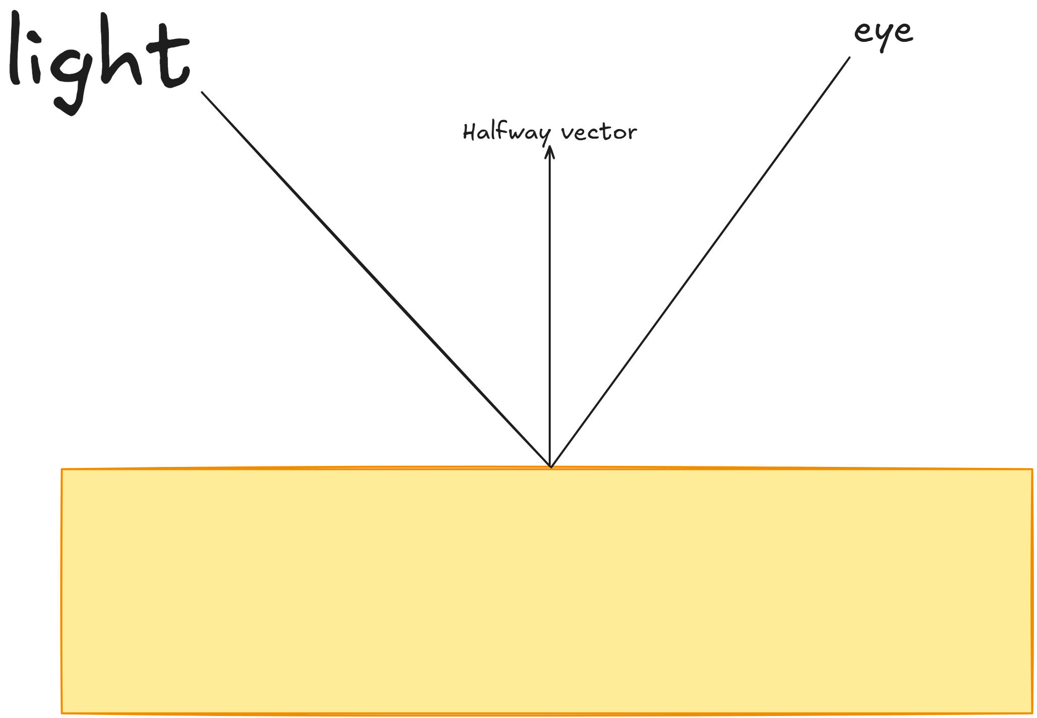
So, more the number of microfacets aligned to the halfway vector, the sharper and stronger the reflection will be, and vice versa.
Energy conservation
If we consider light as a form of energy, when it strikes a surface, the amount of reflected light energy should never exceed the amount of incoming light energy. Because the some amount of energy will get absorbed by the surface.
The moment a light ray hits a surface, it splits into 2 components, one that gets reflected, known as specular light, and another that enters the surface (refracts) known as diffuse light.
In reality, the refracted portion of the light ray does not remain entirely inside the object. It continues to collide with various parts of the object’s material until it loses all of its energy. During this process, some of the refracted light also gets reflected from different points on the surface. For simplicity, we assume that all refracted light is completely absorbed by the surface. Since the reflected amount of energy will never re-enter the surface unless reflected and directed back to the same surface, the energy left for refracted light is the total incoming energy minus the reflected energy. This follows the principle of energy conservation, where the sum of reflected and refracted light energy equals the total incoming energy. In PBR, this balance is crucial for physically accurate shading models.
Surface Interaction Type or BRDF
We now need to consider the type of surface, which determines how each individual light ray contributes to the final reflected light, based on the surface’s material properties. For smooth surfaces, light reflects primarily based on the viewing angle, whereas for rough surfaces, it scatters in multiple directions.
To calculate this, we rely on a standard PBR equation commonly used in real-world applications. This equation is known as the reflectance equation:
\[\begin{align*} L_o(p, \omega_o) = \int_{\Omega} f_r(p, \omega_i, \omega_o)\, L_i(p, \omega_i)\, (\mathbf{n} \cdot \omega_i)\, d\omega_i \end{align*}\]To really understand PBR, it is essential to understand this equation.
This equation calculates the outgoing radiance (magnitude or strength of light) at a point $p$ in direction $\omega_o$. It integrates all incoming light from every direction $\omega_i$ over the hemisphere $\Omega$ above the point $p$, including material’s reflectance and surface orientations.
- $f_r(p, \omega_i, \omega_o)$ is Bidirectional Reflectance Distribution Function (BRDF) which defines the proportion of incoming light from direction $\omega_i$ that is reflected toward direction $\omega_o$, depending on the material at $p$.
- $L_i(p, \omega_i)$ is the incoming radiance at point $p$ from direction $\omega_i$, describing the intensity of light arriving at the surface.
- $(\mathbf{n} \cdot \omega_i)$ is the dot product, which gives the cosine of the angle between surface normal $\mathbf{n}$ and incoming direction $\omega_i$. We consider it to follow the principle that light intensity is strongest when perpendicular to the surface and decreases as the angle becomes more oblique. It scales the energy based on the light’s incidence angle to the surface.
- $d\omega_i$ is a very small solid angle, which is integrated over the hemisphere $\Omega$ to account for contributions from all incoming light directions.
Bidirectional Reflectance Distribution Function (BRDF)
Bidirectional Reflectance Distribution Function (BRDF) is used to simulate the appearance of surfaces under lighting. For this application, we will use the Cook-Torrance BRDF, which is well known and commonly used in real-time PBR pipelines. It accounts for specular reflection, diffuse reflection, and Fresnel effects:
\[\begin{align*} f_r = k_d.f_{lambert} + k_s.f_{cookTorrance} \end{align*}\]Here $k_d$ is ratio of light that gets refracted while $k_s$ is the ratio that gets reflected. $f_{lambert}$ is the Lambertian Diffuse which is a constant denoted as:
\[\begin{align*} f_{lambert} = \frac{c}{\pi} \end{align*}\]where $c$ represents the surface Albedo (color). We divide by $\pi$ to normalize the Lambertian diffuse term, as it accounts for the integral over the hemisphere’s solid angle.
The specular component of the BRDF, $f_{cookTorrance}$ is defined as follows:
\[\begin{align*} f_{cookTorrance} = \frac{D.F.G}{4.(\omega_o \cdot n).(\omega_i \cdot n)} \end{align*}\]Here,
$D$ is a Normal Distribution function which calculates the proportion of microfacets aligned to the halfway vector. We will use a very standard NDF used by multiple game engines for PBR: Trowbridge-Reitz GGX. It is mathematically expressed as:
\[\begin{align*} NDF_{GGXTR}(n, h, \alpha) = \frac{\alpha^2}{\pi ((\mathbf{n} \cdot \mathbf{h})^2 (\alpha^2 - 1) + 1)^2} \end{align*}\]where $h$ represents the halfway vector and $\alpha$ denotes the surface roughness.
In GLSL, we can implement this NDF as follows:
// Distribution function: GGX
float DistributionGGX(vec3 N, vec3 H, float ROUGHNESS)
{
    float a = ROUGHNESS * ROUGHNESS;
    float a2 = a * a;
    float NdotH = max(dot(N, H), 0.0);
    float NdotH2 = NdotH * NdotH;

    float num = a2;
    float denom = (NdotH2 * (a2 - 1.0) + 1.0);
    denom = PI * denom * denom;

    return num / denom;
}
$G$ is Geometry function, which determines how many microfacets are visible from both the view and light directions as sometimes due to roughness some microfacets may block other microfacets, preventing them from reflecting the light. We will use Smith’s Schlick-GGX Geometry Function, standard for calculating geometric occlusion in PBR.
\[\begin{align*} G_{SchlickGGX}(n, v, k) = \frac{n \cdot v}{(n \cdot v) (1 - k)+k} \end{align*}\]where k is similar to $\alpha$ (ROUGHNESS) but with some standard changes depending on direct or Image Based lighting:
\[\begin{align*} k_{direct} = \frac{(\alpha +1)^2}{8} \\ k_{IBL} = \frac{\alpha^2}{2} \end{align*}\]Similarly, we calculate the Geometry function for the light direction, $G_{SchlickGGX}(n, l, k)$ and then combine it with Geometry function for the view direction, $G_{SchlickGGX}(n, v, k)$.
\[\begin{align*} G(n, v, l, k) = G_{SchlickGGX}(n, v, k) * G_{SchlickGGX}(n, l, k) \end{align*}\]In GLSL, we will convert it to code like as follows:
// Geometry function: Smith
float GeometrySchlickGGX(float NdotV, float ROUGHNESS)
{
    float r = (ROUGHNESS + 1.0);
    float k = (r * r) / 8.0;

    float num = NdotV;
    float denom = NdotV * (1.0 - k) + k;

    return num / denom;
}
float GeometrySmith(vec3 N, vec3 V, vec3 L, float ROUGHNESS)
{
    float ggx2 = GeometrySchlickGGX(max(dot(N, V), 0.0), ROUGHNESS);
    float ggx1 = GeometrySchlickGGX(max(dot(N, L), 0.0), ROUGHNESS);

    return ggx1 * ggx2;
}
$F$ is Fresnel equation, which determines the ratio of light that gets reflected versus the amount that is refracted. It also varies over the angle at which we are viewing the surface. We can denote it using Fresnel-Schlick approximation:
\[\begin{align*} F_{Schlick}(h,v,F_0) = F_0 + (1 - F_0)(1-(h\cdot v))^5 \end{align*}\]where $F_0$ represents the base reflectivity of the surface. Since many game engines use 0.04 as the standard base reflectivity value for dielectrics, we will also use $F_0 = 0.04$ in our implementation.
In GLSL, we will implement it as following:
// Calculate reflectance at normal incidence
vec3 F0 = vec3(0.04);
F0 = mix(F0, Albedo, METALNESS);
...
vec3 fresnelTerm = fresnelSchlick(max(dot(H, V), 0.0), F0);
// Fresnel-Schlick approximation
vec3 fresnelSchlick(float cosTheta, vec3 F0)
{
    return F0 + (1.0 - F0) * pow(1.0 - cosTheta, 5.0);
}
Radiance
Next, we have to calculate $L_i(p, \omega_i)$, which represents the incoming radiance at point $p$ from direction $\omega_i$. This radiance is determined by the light source’s position, intensity and direction.
For direct lighting, the radiance function, $L_i(p, \omega_i)$ calculates light contribution at point $p$, accounting for light attenuation due to distance and the relative angle between the surface normal $\mathbf{n}$ and incoming light direction $\omega_i$.
We can integrate it in our fragment shader code as following:
//currPos is world Position here
void main(){
  vec3 N = normalize(Normal);
  vec3 V = normalize(camPos - currPos);
  ...
  vec3 L = normalize(lightPositions[i] - currPos); // light direction
  vec3 H = normalize(V + L); // halfway vector
  float distance = distance(lightPositions[i], currPos);

  float attenuation = 1.0 / distance; // its correct to use 1 / (distance * distance), but for more visual effect I'm using (1 / distance)
  vec3 radiance = attenuation * lightColors[i]; // we will add angular dependency in final lighting calculation
  ...
}
Finally, we combine the Cook-Torrance BRDF calculations with the direct lighting as follows:
// Cook-Torrance BRDF
float NDF = DistributionGGX(N, H, ROUGHNESS);
float G = GeometrySmith(N, V, L, ROUGHNESS);
vec3 fresnelTerm = fresnelSchlick(max(dot(H, V), 0.0), F0);

vec3 numerator = NDF * G * fresnelTerm;
float denominator = 4.0 * max(dot(N, V), 0.0) * max(dot(N, L), 0.0) + 0.001; // adding 0.001 so we will not divide numerator by 0
vec3 specular = numerator / denominator;

vec3 kS = fresnelTerm; // specular reflection
vec3 kD = vec3(1.0) - kS; // diffuse reflection
kD *= 1.0 - METALNESS;

float NdotL = max(dot(N, L), 0.0);

directLighting += (kD * Albedo / PI + specular) * radiance * NdotL;
We can return FragColor with this directLighting or mix it with Albedo.
vec3 ambient = vec3(0.03) * Albedo * ao;
vec3 color = directLighting + ambient;
...
FragColor = vec4(color, 1.0);
At this point, you should be able to see the spheres rendered with direct lighting and PBR enabled. It will look more realistic and physically accurate appearance.
For this setup, I have implemented nine lights moving in a circular path at variable speeds. You can define the number of lights, their positions, colors, and other properties as desired.
I will share the output I achieved with this setup.
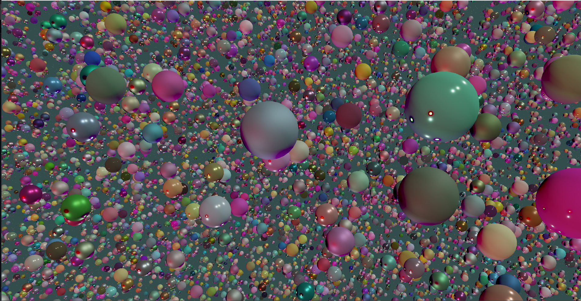
With this, we have completed the implementation of PBR with direct lighting.
In the next blog, we will cover Image Based Lighting (IBL), the final part of our implmentation.