Image Based Lighting: Part 1 (Diffuse IBL)
Image Based Lighting (IBL) is a technique used in computer graphics and rendering to light objects using information from images representing the surrounding environment as one big light source. IBL uses an image, usually a high dynamic range image (HDRI) or a cubemap environment texture, captured from the real world to simulate a realistic lighting environment.
Imagine a reflective object placed outdoors. IBL simulates how the object interacts with the entire environment, including the sky, buildings, and other surrounding elements, creating realistic reflections and lighting effects.
Before proceeding, let’s take a look at reflectance equation.
\[\begin{align*} L_o(p, \omega_o) = \int_{\Omega} \left( k_d \frac{c}{\pi} + k_s \frac{DFG}{4(\omega_o \cdot n)(\omega_i \cdot n)} \right) L_i(p, \omega_i) (n \cdot \omega_i) \, d\omega_i \end{align*}\]IBL considers whole environment lighting rather than just direct lighting, which makes it possible for objects to appear more physically accurate. In the case of environment lighting, calculating radiance using the reflectance equation requires integrating it across all incoming light directions over the hemisphere above the surface because of potential radiance contributions from all possible directions. While for direct lighting, we already know the limited light positions and their corresponding directions which make it easier to calculate radiance as it originates from a single direction.
With an environment cubemap, each texel (texture pixel) can be visualized as one single light source. By sampling this cubemap with texture() for the direction $\omega_i$, we can get the scene’s radiance from that direction.
vec3 radiance = texture(cubemap, w_i).rgb;
We have to do this sampling for all possible directions $\omega_i$ across the hemisphere $\Omega$ which can become computationally expensive for each fragment shader call. To solve this integral efficiently, we will precompute most of the required calculations.
The reflectance equation can be split into two separate components: diffuse and specular IBL.
\[\begin{align*} L_o(p, \omega_o) = \int_{\Omega} (k_d \frac{c}{\pi}) L_i(p, \omega_i) (n \cdot \omega_i) \, d\omega_i + \int_{\Omega}(k_s \frac{DFG}{4(\omega_o \cdot n)(\omega_i \cdot n)}) L_i(p, \omega_i) (n \cdot \omega_i) \, d\omega_i \end{align*}\]Diffuse IBL
In the integral for Diffuse IBL, the constant term $k_d\frac{c}{\pi}$ can be factored out of the integration. For precomputation, we assume that the point $p$ is always at the center of the environment cubemap. This assumption gives us an integral which is totally dependent on $\omega_i$. Now, we can compute a new cubemap which will store the result of diffuse integral for all possible outgoing directions $\omega_o$ using convolution.
Convolution involves performing calculations for each entry in a dataset while accounting for contributions from all other entries in the dataset. In this context, for every sample direction in the cubemap, we account for contributions from all other sample directions across the hemisphere $\Omega$.
To perform convolution on this environment cubemap, we will solve the integral for each output direction $\omega_o$ by sampling multiple incoming directions $\omega_i$. The radiance from these sampled directions is then averaged to compute the convolution result. The hemisphere $\Omega$ used for sampling $\omega_i$ is always aligned with the specific outgoing direction $\omega_o$ being convolved.
This precomputed cubemap represents the sum of all indirect diffuse light from the scene that interacts with the surface aligned along the outgoing direction $\omega_o$. This type of cubemap is commonly reffered to as an irradiance map, as it enables direct sampling of scene’s irradiance for any outgoing direction $\omega_o$. Think of the irradiance map like a precomputed lighting guide that can tell the shader how much diffuse light is coming from every direction, saving computation time during rendering.
Cubemap
We can think of the cubemap as a virtual skybox that surrounds your scene, providing lighting and reflections that mimic a real-world environment. To generate a cubemap, we can either use a skybox consisting of six images for the six faces of a cube or an HDR image. However, for PBR implementation, we must have to use HDR images. Unlike normal LDR images, which have RGB values constrained between 0.0 and 1.0, HDR images feature color values outside this range, enabling accurate representation of light intensity too. I used the HDR image shown below, but you can choose any freely available HDR images online.
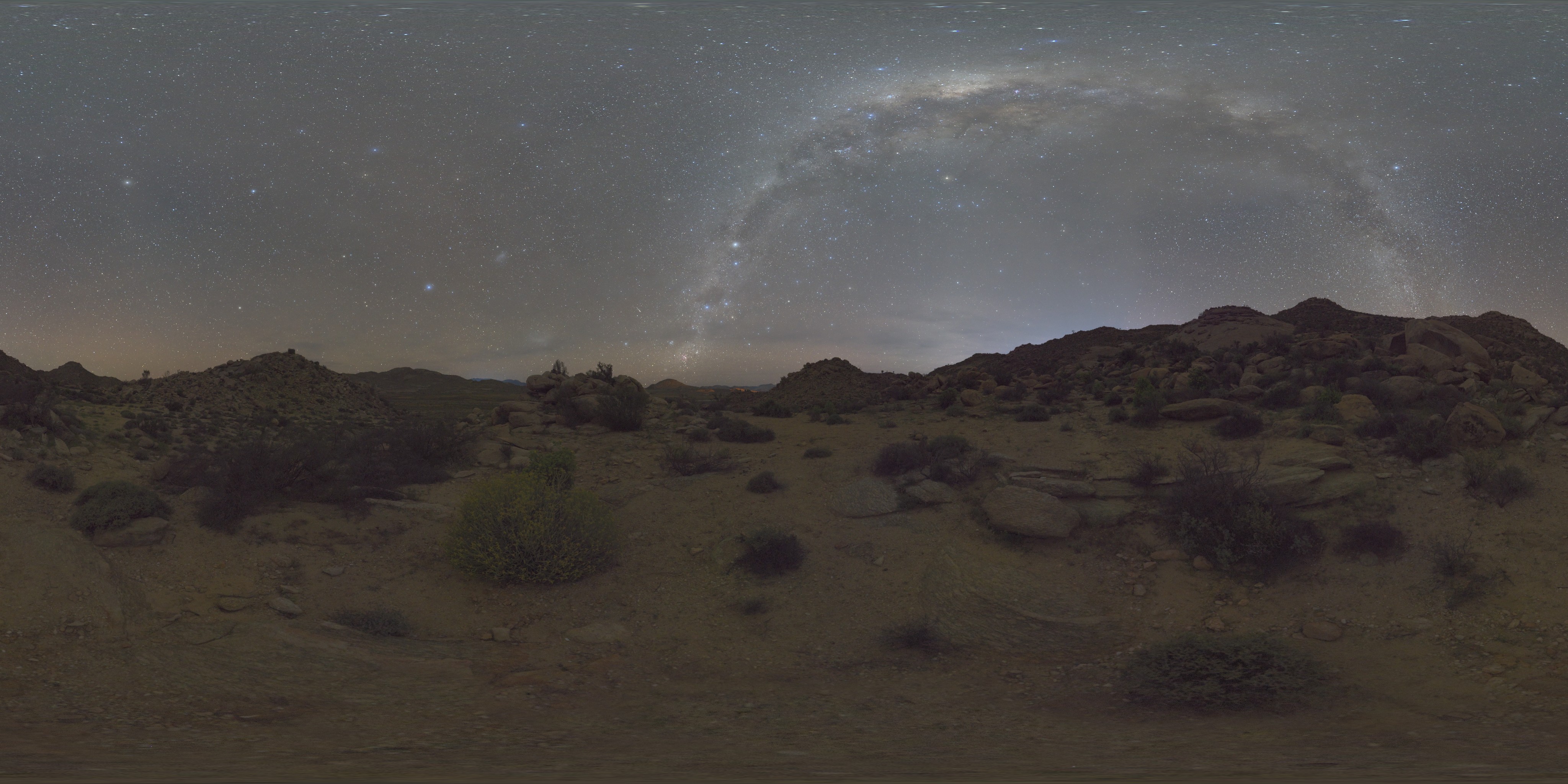 This image may appear slightly distorted in certain areas because it is projected from a sphere onto a flat plane. This projection allows us to visualize and store the image as a single equirectangular map.
Now we have to convert this HDR image into an environment cubemap. First, we will load it using the standard stb_image.h library, which supports loading .hdr images as arrays of floating-point values. We need to add a new constructor to our existing Texture class, which was introduced in the 3D basics blog. This constructor will support loading of .hdr image.
Texture::Texture(const char* imagePath, GLenum slot)
{
	type = "HDR";

	int width, height, numChannels;
	stbi_set_flip_vertically_on_load(true);
	float* bytes = stbi_loadf(imagePath, &width, &height, &numChannels, 0);

	if (!bytes) {
		std::cerr << "Failed to load HDR texture at path: " << imagePath << std::endl;
		return;
	}
	else {
		std::cout << imagePath << " loaded correctly.\n";
	}

	glGenTextures(1, &ID);
	glActiveTexture(slot);
	glBindTexture(GL_TEXTURE_2D, ID);

	// Load HDR bytes into the texture
	glTexImage2D(GL_TEXTURE_2D, 0, GL_RGB16F, width, height, 0, GL_RGB, GL_FLOAT, bytes);

	// Set texture parameters
	glTexParameteri(GL_TEXTURE_2D, GL_TEXTURE_WRAP_S, GL_CLAMP_TO_EDGE);
	glTexParameteri(GL_TEXTURE_2D, GL_TEXTURE_WRAP_T, GL_CLAMP_TO_EDGE);
	glTexParameteri(GL_TEXTURE_2D, GL_TEXTURE_MIN_FILTER, GL_LINEAR);
	glTexParameteri(GL_TEXTURE_2D, GL_TEXTURE_MAG_FILTER, GL_LINEAR);

	stbi_image_free(bytes);
	glBindTexture(GL_TEXTURE_2D, 0);
}
// In main.cpp
Texture hdrTexture("./textures/night.hdr", GL_TEXTURE0);
Once the HDR image is loaded and its Texture object is created, we need to generate its cubemap. To convert an equirectangular image into a cubemap, we render a cube, project the equirectangular map onto its faces, and capture six images representing the cube’s sides as cubemap faces.
We will create a new class TextureUtilities, which will contain functions such as GenerateCubemap(), GenerateIrradianceMap(), and others. The TextureUtilities class will have a shared cube (skybox) mesh for generating these maps, as well as a common View-Projection Camera matrix.
class TextureUtilities {
public:
    TextureUtilities();

    glm::mat4 captureProjection; // projection Matrix
    std::vector<glm::mat4> captureViews; // vector array of View Matrix (for 6 cube faces)
    std::vector<glm::mat4> cameraMatrix; // Camera Matrix (View x Projection Matrix)

    std::vector<glm::vec3> skyboxVertices = {
        // positions
        glm::vec3(1.0f,  1.0f, 1.0f),
        glm::vec3(1.0f, -1.0f, 1.0f),
        glm::vec3(-1.0f, -1.0f, 1.0f),
        glm::vec3(-1.0f, 1.0f, 1.0f),
        glm::vec3(1.0f, 1.0f, -1.0f),
        glm::vec3(1.0f, -1.0f, -1.0f),
        glm::vec3(-1.0f, -1.0f, -1.0f),
        glm::vec3(-1.0f, 1.0f, -1.0f),
    };
    std::vector<GLuint> skyboxIndices = {
        0, 1, 2,
        2, 3, 0,

        0, 3, 4,
        3, 4, 7,

        2, 3, 6,
        3, 6, 7,

        0, 1, 5,
        0, 4, 5,

        1, 2, 5,
        2, 5, 6,

        4, 5, 6,
        4, 6, 7
    };
    Mesh* skymap;

	GLuint GenerateCubemap(GLuint &hdrTexture, Shader& shader);
	GLuint GenerateIrradianceMap(GLuint &cubemapTexture, Shader& irradianceShader);
	GLuint GeneratePrefilteredCubemap(GLuint &cubemapTexture, Shader& prefilterShader, GLuint maxMipLevels);
	GLuint GenerateBRDFLUT(Shader &brdfShader);
};
Inside the TextureUtilities() constructor, we will initialize the skymap pointer with new Mesh(skyboxVertices, skyboxIndices) and set up the cameraMatrix.
TextureUtilities::TextureUtilities()
{
    captureProjection = glm::perspective(glm::radians(90.0f), 1.0f, 0.1f, 10.0f); // fov of 90 degrees to capture the entire face

    captureViews.push_back(glm::lookAt(glm::vec3(0.0f), glm::vec3(1.0f, 0.0f, 0.0f), glm::vec3(0.0f, -1.0f, 0.0f))); // Positive X (+X) axis
    captureViews.push_back(glm::lookAt(glm::vec3(0.0f), glm::vec3(-1.0f,  0.0f,  0.0f), glm::vec3(0.0f, -1.0f,  0.0f))); // Negative X (-X) axis
    captureViews.push_back(glm::lookAt(glm::vec3(0.0f), glm::vec3(0.0f, 1.0f, 0.0f), glm::vec3(0.0f, 0.0f, 1.0f))); // Positive Y (+Y) axis
    captureViews.push_back(glm::lookAt(glm::vec3(0.0f), glm::vec3(0.0f, -1.0f, 0.0f), glm::vec3(0.0f, 0.0f, -1.0f))); // Negative Y (-Y) axis
    captureViews.push_back(glm::lookAt(glm::vec3(0.0f), glm::vec3(0.0f, 0.0f, 1.0f), glm::vec3(0.0f, -1.0f, 0.0f))); // Positive Z (+Z) axis
    captureViews.push_back(glm::lookAt(glm::vec3(0.0f), glm::vec3(0.0f, 0.0f, -1.0f), glm::vec3(0.0f, -1.0f, 0.0f)));  // Negative Z (-Z) axis

    cameraMatrix.resize(6, glm::mat4(1.0f));

    for (int i = 0; i < 6; i++) {
        cameraMatrix[i] = captureProjection * captureViews[i];
    }

    skymap = new Mesh(skyboxVertices, skyboxIndices);
}
Before we start implementing GenerateCubeMap(), we need to create new vertex and fragment shader, which will help in projecting the equirectangular map onto each face of the cubemap.
The vertex shader will not modify anything, it will simply pass the local positions to the fragment shader without any modifications.
// cubeMapShader.vert
#version 330 core
layout (location = 0) in vec3 aPos;

out vec3 localPos;

uniform mat4 camMatrix; // View x Projection Matrix

void main()
{
    localPos = aPos;
    gl_Position = camMatrix * vec4(aPos, 1.0);
}
In the fragment shader, we will project the equirectangular map onto the cube faces by converting the localPos 3D vector into spherical UV coordinates, which will then be used to sample the texture.
#version 330 core

in vec3 localPos; // local position passed from vertex shader
out vec4 FragColor;

uniform sampler2D hdrTexture; // equirectangular map

const vec2 invAtan = vec2(0.1591, 0.3183); // constants used for inverse trigonometric scaling to map spherical coordinates to UV space

vec2 SampleSphericalMap(vec3 v)
{
    vec2 uv = vec2(atan(v.z, v.x), asin(v.y)); // atan calculates longitude and asin calulates latitude
    uv *= invAtan; // scaling to fit the UV space
    uv += 0.5; // offset for maintaining the UV range
    return uv;
}

void main() {
    vec2 uv = SampleSphericalMap(normalize(localPos)); // calculate uv coordinates
    vec3 color = texture(hdrTexture, uv).rgb; // sample the hdrtexture to retrieve color at the uv direction

    FragColor = vec4(color, 1.0);
}
Next, we create a ShaderClass object using these two shaders and pass it to GenerateCubemap() function.
Shader cubemapShader("./cubemapShader.vert", "./cubemapShader.frag", "cubemap");
cubemapShader.Activate();
...
GLuint cubemapTexture = textureUtilitiesObject.GenerateCubemap(hdrTexture.ID, cubemapShader);
Now we can start writing GenerateCubemap function which will generate a cubemap from provided HDR texture and this shader. The function begins by initializing the cubemapTexture, allocating memory for each cube face, and configuring standard texture parameters. Next, we set up the framebuffer and renderbuffer objects, bind the HDR texture, and attach the shader. Finally, we draw the HDR texture onto each cubemap face.
GLuint TextureUtilities::GenerateCubemap(GLuint& hdrTexture, Shader &shader)
{
    GLuint cubemapTexture;
    glGenTextures(1, &cubemapTexture);
    glBindTexture(GL_TEXTURE_CUBE_MAP, cubemapTexture); // GL_TEXTURE_CUBE_MAP for storing 6 2d images corresponding to cube faces

    for (GLuint i = 0; i < 6; ++i) {
        glTexImage2D(GL_TEXTURE_CUBE_MAP_POSITIVE_X + i, 0, GL_RGB16F, 512, 512, 0, GL_RGB, GL_FLOAT, nullptr); //Memory allocation
    }

    glTexParameteri(GL_TEXTURE_CUBE_MAP, GL_TEXTURE_WRAP_S, GL_CLAMP_TO_EDGE);
    ... // other parameters

    GLuint captureFBO, captureRBO;
    glGenFramebuffers(1, &captureFBO); // generate 1 frame buffer object (framebuffer = color buffer + depth buffer + stencil buffer)
    glGenRenderbuffers(1, &captureRBO); // generate 1 reader buffer object (render buffer will store depth info)

    glBindFramebuffer(GL_FRAMEBUFFER, captureFBO);
    glBindRenderbuffer(GL_RENDERBUFFER, captureRBO);
    glRenderbufferStorage(GL_RENDERBUFFER, GL_DEPTH_COMPONENT24, 512, 512);
    glFramebufferRenderbuffer(GL_FRAMEBUFFER, GL_DEPTH_ATTACHMENT, GL_RENDERBUFFER, captureRBO);

    glViewport(0, 0, 512, 512);

    shader.Activate();
    glActiveTexture(GL_TEXTURE0);
    glBindTexture(GL_TEXTURE_2D, hdrTexture);
    glUniform1i(glGetUniformLocation(shader.ID, "hdrTexture"), 0); // assigning shader uniform hdrTexture

    glBindFramebuffer(GL_FRAMEBUFFER, captureFBO);


    for (GLuint i = 0; i < 6; ++i) {
        glUniformMatrix4fv(glGetUniformLocation(shader.ID, "camMatrix"), 1, GL_FALSE, glm::value_ptr(cameraMatrix[i])); // setting uniform cameraMatrix with specific cameraMatrix[i]

        glFramebufferTexture2D(GL_FRAMEBUFFER, GL_COLOR_ATTACHMENT0, GL_TEXTURE_CUBE_MAP_POSITIVE_X + i, cubemapTexture, 0); // attaching frame buffer with current cubemap face(+/-X, +/-Y, +/-Z) and texture image
        glClear(GL_COLOR_BUFFER_BIT | GL_DEPTH_BUFFER_BIT);

        skymap->Draw(shader);
    }

    glBindFramebuffer(GL_FRAMEBUFFER, 0);
    return cubemapTexture;
}
The Draw function is defined as
void Mesh::Draw(Shader& shader) const
{
    mainVAO.Bind();

    glDrawElements(GL_TRIANGLES, GLsizei(indices.size()), GL_UNSIGNED_INT, 0);
}
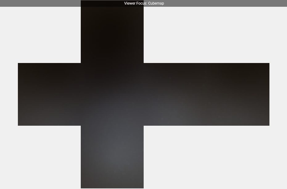
It should generate a cubemap like the following image:
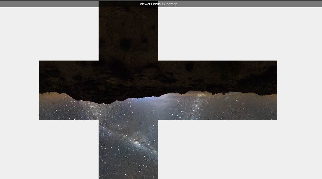 I took this screenshot from Nvidia’s Nsight Graphics 2025.2.0 Frame debugger window. It’s a great tool for debugging, profiling, analyzing resource utilization and other activities.
To render the cubemap as a skymap, we need to create new shaders. The vertex shader, skymap.vert, will simply pass the localPos 3D vector to the fragment shader.
#version 330 core
layout (location = 0) in vec3 aPos;

uniform mat4 camMatrix;

out vec3 localPos;

void main()
{
    localPos = aPos;
    vec4 pos = camMatrix * vec4(aPos, 1.0);
    gl_Position = pos.xyww; // Depth is set far away
}
The fragment shader samples the cubemap using localPos and applies standard gamma correction. Gamma correction ensures that the rendered skybox appears visually consistent across different display devices by compensating for non-linear color intensity.
#version 330 core
in vec3 localPos;

uniform samplerCube skybox;

out vec4 FragColor;

void main()
{
    vec3 color = texture(skybox, localPos).rgb;

    color = color / (color + vec3(1.0));
    color = pow(color, vec3(1.0/2.2));

    FragColor = vec4(color, 1.0);
}
Next, we need to create a ShaderClass object for the skybox and a separate Mesh for rendering.
// In main.cpp
//*****************-------SkyMap----------*****************

Shader skymapShader("./skymap.vert", "./skymap.frag", "skybox");
skymapShader.Activate();

std::vector<glm::vec3> skyboxVertices = {
    // positions
    glm::vec3(300.0f,  300.0f, 300.0f),
    glm::vec3(300.0f, -300.0f, 300.0f),
    ...
};
std::vector<GLuint> skyboxIndices = {
    0, 1, 2,
    2, 3, 0,
    ...
};

Mesh skymap(skyboxVertices, skyboxIndices);
...
while(true){
    ...
    glDepthFunc(GL_LEQUAL); // to pass when incoming depth is less or equal to stored
    skymap.Draw(skymapShader, camera, cubemapTexture);
    glDepthFunc(GL_LESS);
    ...
}
The result should render as a skybox, creating a continuous-looking environment.
With the cubemap generated from the HDR image and rendered in our application, we can now proceed to generate the previously discussed irradiance map.
Irradiance Map
Now that we have an environment cubemap, we can sample it for a specific direction $\omega_i$ to calculate radiance $L(p, \omega_i)$. However, we now have to face the challenge of solving the integral for all possible incoming directions.
As discussed earlier, we will precompute and store the necessary calculations in an irradiance map. The radiance value can then be obtained by sampling the irradiance map for the fragment’s surface, oriented along its surface normal.
vec3 irradiance = texture(irradianceMap, N).rgb;
To generate the irradiance map, we need to perform convolution on the environment lighting coming from the cubemap. The surface hemisphere is oriented along the normal, and convoluting the cubemap corresponds to calculating the total averaged radiance for each direction $\omega_i$ in the hemisphere $\Omega$ oriented along $N$.
As before, we will begin by writing vertex and fragment shaders, to perform convolution and generate the irradiance map. For the vertex shader, you can either reuse the previous cubeMapShader.vert file or create a new irradianceShader.vert file containing the same content.
Before writing the fragment shader code, we need to understand how convolution will be performed. The solid angle $dw$ will be defined based on the number of segments in the hemisphere $\Omega$. To utilize the solid angle, we must convert it into its equivalent spherical coordinates, represented as $sin(\theta) d\theta d\phi$. This conversion is explained in the Spheres section of the Circle, Sphere and Spheres blog.
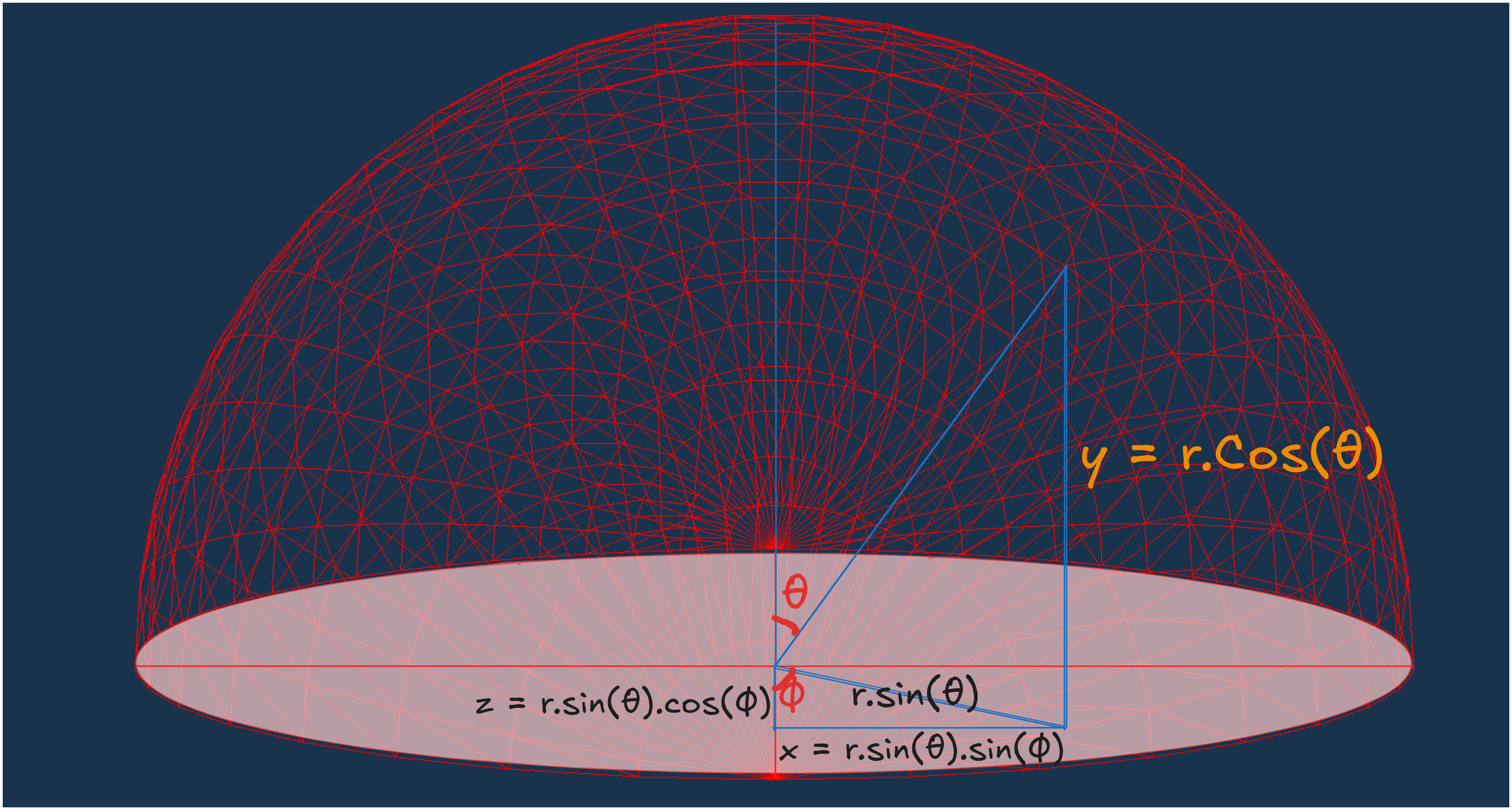 We can assume that $d\omega$ has a height of $d\theta$ and a width of $sin(\theta)d\phi$ (where $sin(\theta)$ swept over $d\phi$). The area covered will be $sin(\theta)d\phi \times d\theta $, which is equal to the solid angle $d\omega$.
Using this approach, we can rewrite the reflectance equation in terms of $\theta$ and $\phi$.
\[\begin{align*} L_o(p, \phi_o, \theta_o) = k_d \frac{c}{\pi} \int_{\phi = 0}^{2\pi}\int_{\theta = 0}^{\frac{\pi}{2}} L_i(p, \phi_i, \theta_i) cos(\theta)sin(\theta)d\phi d\theta \end{align*}\]Now we can write the fragment shader, keeping the above method in mind.
#version 330 core
out vec4 FragColor;
in vec3 localPos;

uniform samplerCube environmentMap;

const float PI = 3.14159265359;

void main()
{
    vec3 N = normalize(localPos); // normal for hemisphere's orientation

    vec3 irradiance = vec3(0.0);

    vec3 up    = vec3(0.0, 1.0, 0.0); // Up vector
    vec3 right = normalize(cross(up, normal)); // right Direction vector
    up         = normalize(cross(N, right));

    float sampleDelta = 0.025;
    float sampleCount = 0;
    for(float phi = 0.0; phi < 2.0*PI; phi+=sampleDelta){
        for(float theta = 0.0; theta < 0.5*PI; theta+=sampleDelta){
            // spherical to cartesian coordinates in tangent space
            vec3 tangentSample = vec3(sin(theta) * cos(phi),  sin(theta) * sin(phi), cos(theta));
            // tangent space to world space coordinates
            vec3 sampleVec = tangentSample.x * right + tangentSample.y * up + tangentSample.z * N;
            // sample the envMap and add it to irradiance
            irradiance += texture(environmentMap, sampleVec).rgb * cos(theta) * sin(theta); // cos(theta) to account that light becomes weaker at larger angles & sin(theta) accounts smaller sample areas in higher hemisphere areas.
            sampleCount++;
        }
    }
    irradiance = irradiance * (PI / float(sampleCount)); // Normalize by sample count

    FragColor = vec4(irradiance, 1.0); // Output irradiance
}
Next, we create another ShaderClass object for the irradianceShader and call the generateIrradianceMap function with this shader and the previously generated cubemap texture.
Shader irradianceShader("./irradianceShader.vert", "./irradianceShader.frag", "irradiancemap");
irradianceShader.Activate();
...
GLuint irradianceMap = textureUtilitiesObject.GenerateIrradianceMap(cubemapTexture, irradianceShader);
glViewport(0, 0, WIDTH, HEIGHT);
We will implement the GenerateIrradianceMap() in a similar manner to GenerateCubeMap() just with a few differences which I’ll highlight in the code comments.
GLuint TextureUtilities::GenerateIrradianceMap(GLuint& cubemapTexture, Shader& irradianceShader)
{
    GLuint irradianceMap;
    glGenTextures(1, &irradianceMap);
    glBindTexture(GL_TEXTURE_CUBE_MAP, irradianceMap); // GL_TEXTURE_CUBE_MAP same as GenerateCubeMap()

    for (GLuint i = 0; i < 6; ++i) {
        glTexImage2D(GL_TEXTURE_CUBE_MAP_POSITIVE_X + i, 0, GL_RGB16F, 32, 32, 0, GL_RGB, GL_FLOAT, nullptr); // Notice the difference in size (32 x 32) as irradiance map will not have high frequency details because of the averaging of sorrounding radiance
    }

    glTexParameteri(GL_TEXTURE_CUBE_MAP, GL_TEXTURE_WRAP_S, GL_CLAMP_TO_EDGE);
    ...

    GLuint captureFBO, captureRBO;
    glGenFramebuffers(1, &captureFBO);
    glGenRenderbuffers(1, &captureRBO);

    glBindFramebuffer(GL_FRAMEBUFFER, captureFBO);
    glBindRenderbuffer(GL_RENDERBUFFER, captureRBO);
    glRenderbufferStorage(GL_RENDERBUFFER, GL_DEPTH_COMPONENT24, 32, 32); // again storing the map at lower resolution
    glFramebufferRenderbuffer(GL_FRAMEBUFFER, GL_DEPTH_ATTACHMENT, GL_RENDERBUFFER, captureRBO);

    if (glCheckFramebufferStatus(GL_FRAMEBUFFER) != GL_FRAMEBUFFER_COMPLETE) {
        std::cerr << "Framebuffer is not complete!" << std::endl;
        return 0; // Return an invalid texture
    }

    glViewport(0, 0, 32, 32); // resize the viewport to capture all dimensions

    // Activate the irradiance shader
    irradianceShader.Activate(); // shader with convolution calculations
    glActiveTexture(GL_TEXTURE0);
    glBindTexture(GL_TEXTURE_CUBE_MAP, cubemapTexture); // Bind the input cubemap texture
    glUniform1i(glGetUniformLocation(irradianceShader.ID, "environmentMap"), 0);

    glBindFramebuffer(GL_FRAMEBUFFER, captureFBO);

    for (GLuint i = 0; i < 6; ++i) {
        glUniformMatrix4fv(glGetUniformLocation(irradianceShader.ID, "camMatrix"), 1, GL_FALSE, glm::value_ptr(cameraMatrix[i]));

        glFramebufferTexture2D(GL_FRAMEBUFFER, GL_COLOR_ATTACHMENT0, GL_TEXTURE_CUBE_MAP_POSITIVE_X + i, irradianceMap, 0);
        glClear(GL_COLOR_BUFFER_BIT | GL_DEPTH_BUFFER_BIT);

        skymap->Draw(irradianceShader);
    }

    glBindFramebuffer(GL_FRAMEBUFFER, 0);
    return irradianceMap;
}
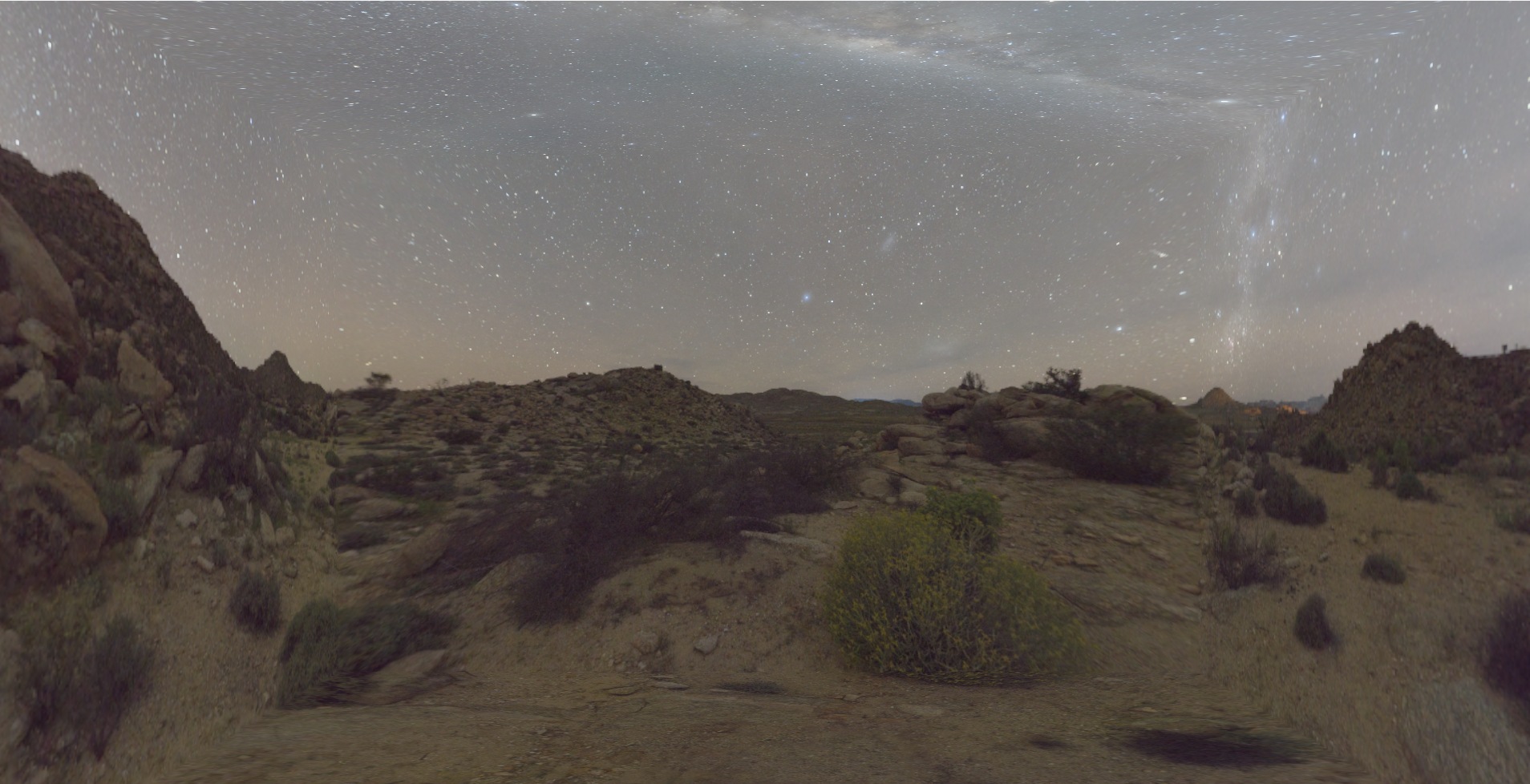
It should generate an irradiance map similar to the one shown below.
PBR and diffuse IBL
Before starting the specular part of IBL, we should complete the integration of diffuse IBL with PBR in the pre-existing shader code. Since both specular and diffuse IBL are components of indirect lighting, we can replace ambient lighting with them.
We begin by passing the pre-generated irradiance map as a uniform, and then retrieve the stored irradiance values by sampling the texture (irradiance map) around the surface normal. Next, we use the Fresnel equation to adjust the weight of the diffuse part of IBL. However, in this case, we do not have a halfway vector since we are considering light contributions from all possible directions around the hemisphere. This can be addressed by using the ROUGHNESS term, as the halfway vector was previously used to represent roughness. Finally, we add the computed diffuse IBL to the final color.
...
uniform samplerCube irradianceMap; // Diffuse irradiance
...
vec3 fresnelSchlickRoughness(float cosTheta, vec3 F0, float roughness)
{
    return F0 + (max(vec3(1.0 - roughness), F0) - F0) * pow(clamp(1.0 - cosTheta, 0.0, 1.0), 5.0);
}
...
void main(){
    ...
    vec3 F = fresnelSchlickRoughness(max(dot(N, V), 0.0), F0, ROUGHNESS);

    vec3 kS = F;
    vec3 kD = 1.0 - kS;
    kD *= 1.0 - METALNESS;

    // DIFFUSE IBL
    vec3 irradiance = texture(irradianceMap, N).rgb;
    vec3 diffuseIBL = irradiance * Albedo;

    // AMBIENT IBL
    vec3 ambientIBL = (kD * diffuseIBL) * ao;
    ...
    vec3 color = ambientIBL;
    ...
    FragColor = vec4(color, 1.0);
}
It should give output like the following image:
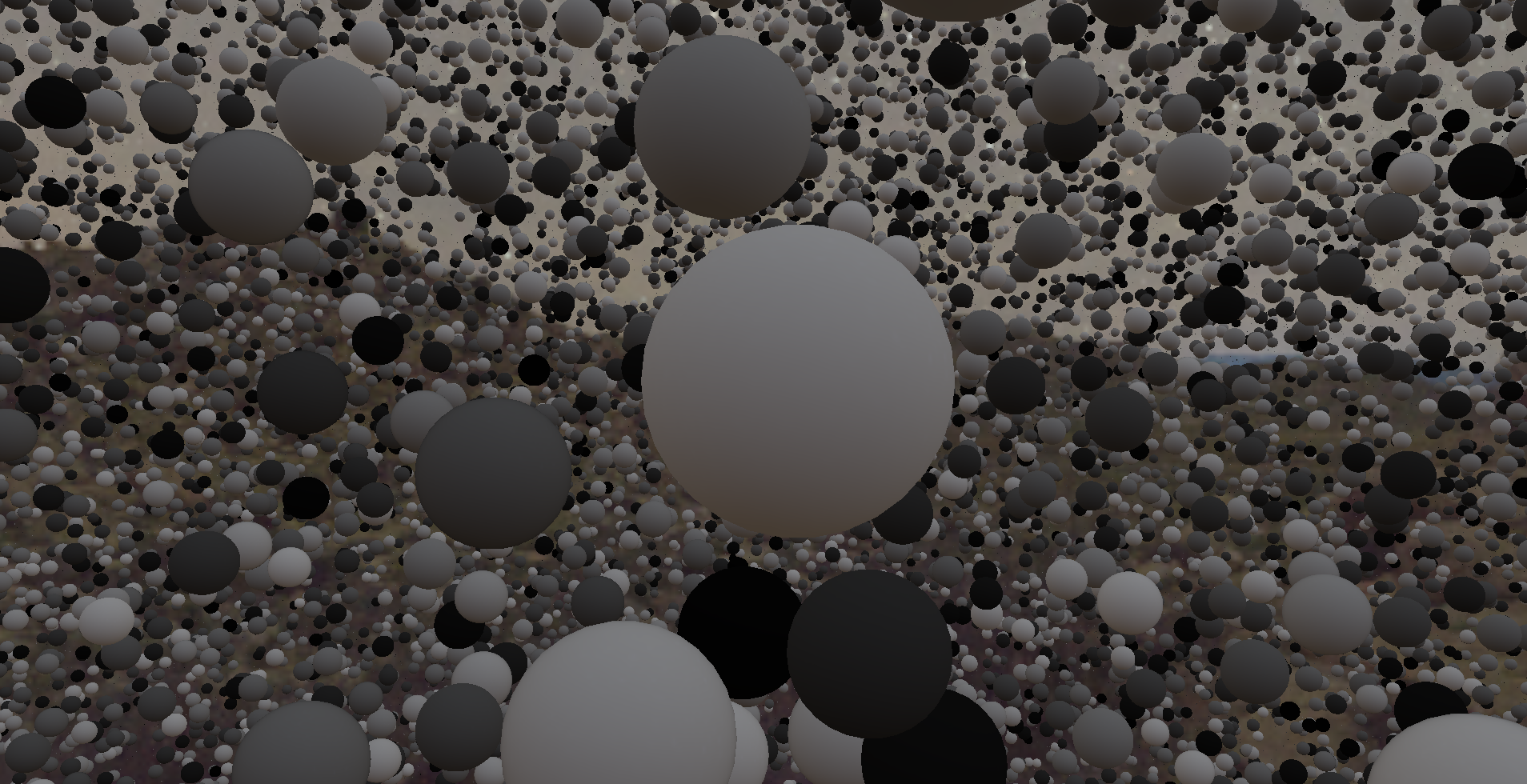 In this output, I have disabled the direct lighting to better illustrate the diffuse IBL.
Now we are left with the specular part of IBL, which I will complete in the next blog as this one has already crossed a good length.